

Meters and protective relays need electrical signals that match their input ratings. Connecting a low-voltage measuring circuit directly to a high-voltage bus or a large primary current would be unsuitable and unsafe. Instrument transformers provide scaled secondary signals for metering, monitoring, and protection, while separating the instrument circuit from the primary power circuit through an insulation system designed for the application. The two principal types are current transformers (CTs) and voltage transformers (VTs); their roles and connection methods differ.
HOW CURRENT AND VOLTAGE TRANSFORMERS WORK
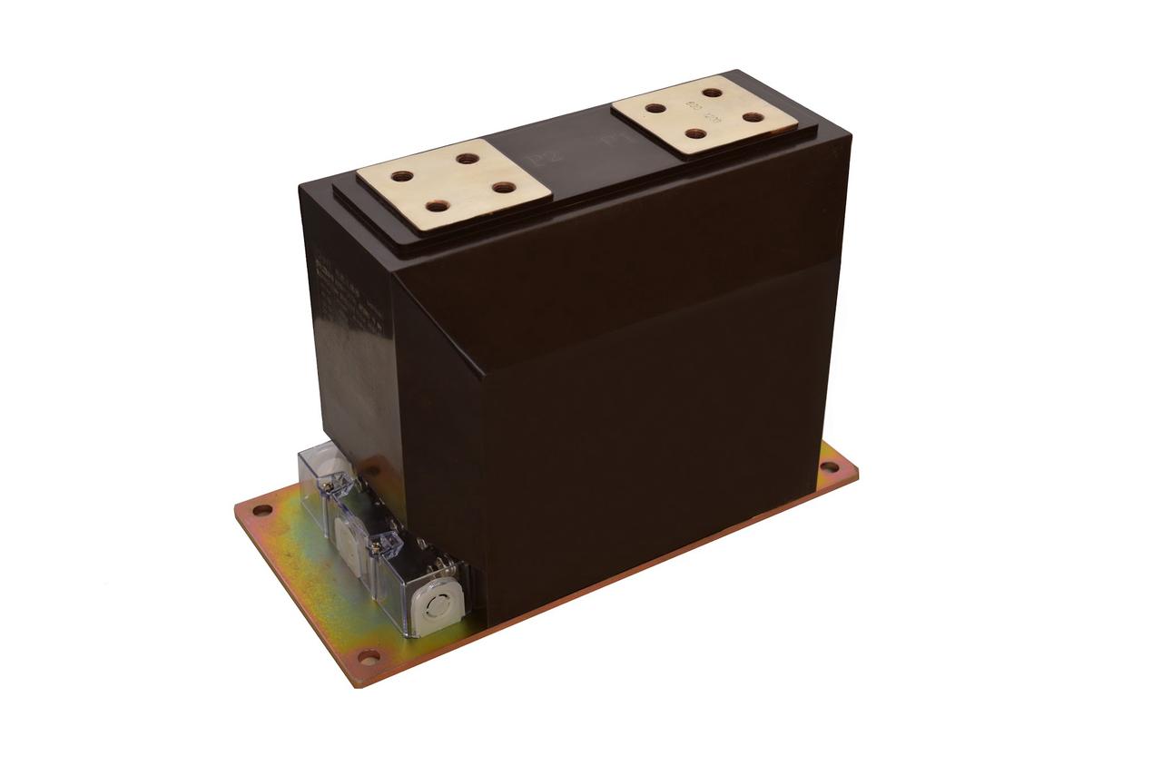
A CT is installed in series with the conductor or bus whose current is being measured. It reproduces primary current as a lower secondary current at a defined ratio. A VT is connected across the circuit and reproduces primary voltage as a lower secondary voltage. Depending on region and product documentation, voltage transformers may also be called potential transformers (PTs). Neither device is a power transformer for feeding ordinary loads: each is intended to provide a measurement or protection signal to connected equipment.
The output is useful only when the transformer is matched to the connected meter, relay, or control device. The primary and secondary ratings establish the nominal ratio; accuracy and performance are affected by the connected burden and by the transformer’s design. A low-voltage secondary does not mean that the primary circuit has become safe to approach. Isolation, clearances, grounding, barriers, and work procedures remain essential parts of the installation.
CTs and VTs may contain separate secondary windings or cores for different duties. For example, a metering circuit and a protection circuit can require different accuracy and transient performance. A design should not assume that one winding can serve every instrument equally well. The selected product documentation defines the intended use, rating, accuracy, burden, insulation, and permitted secondary connections.
WHERE INSTRUMENT TRANSFORMERS ARE USED
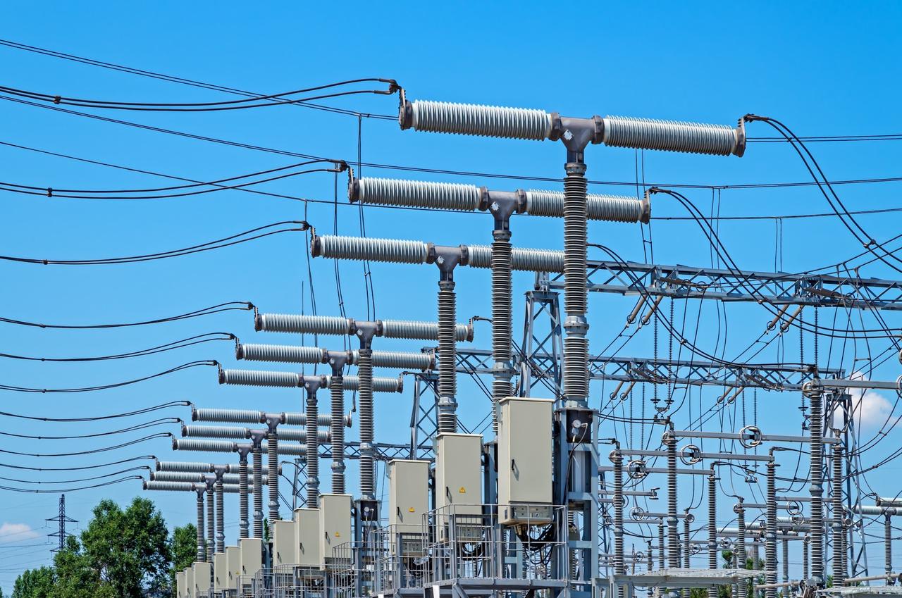
In a substation, instrument transformers provide current and voltage signals for protective relays, revenue or operational metering, indication, and supervisory systems. A CT can feed a protective relay that detects current outside its configured operating limits; the relay evaluates the signal and issues a trip command through the control circuit when its logic is satisfied. The instrument transformer itself does not detect a fault or interrupt current. The breaker and protection system perform those functions.
In industrial switchgear and power-distribution equipment, CTs and VTs support ammeters, voltmeters, power meters, energy meters, power-quality instruments, and protection relays. The exact arrangement depends on voltage class, panel design, grounding, and the signals required by the control scheme. A switchboard may use low-voltage current transformers for metering, while medium- or high-voltage installations use instrument transformers designed for their specific insulation and system conditions.
The application also affects the accuracy requirement. A revenue-metering circuit may need accuracy across a defined operating range; a protection CT must reproduce fault-current behavior sufficiently for the selected relay scheme. Their performance cannot be reduced to a single “more accurate” label. Engineers should match the accuracy class and rated burden to the instrument, wiring, and expected operating range, then confirm the arrangement using the governing project standard and utility requirements. IEC 61869-1:2023 sets general requirements for instrument transformers within its stated scope; the relevant part-specific standard and local rules also need review.
SELECT THE CORRECT TYPE AND RATING
Start with the one-line diagram and instrument schedule. Confirm the system voltage and frequency, maximum operating conditions, required primary current or voltage ratio, secondary rating, number of cores or windings, insulation level, installation location, and connected devices. Check the rated burden, accuracy class, thermal or short-time current requirements, and any protection-specific performance values stated by the design. The same ratio on two products does not guarantee that they are interchangeable.
For a CT, the engineer should verify the primary conductor arrangement, polarity, secondary rating, metering or protection class, burden, and short-time withstand duty. Protection applications may require assessment of saturation behavior against the maximum fault current and relay settings. For a VT, confirm the primary and secondary voltage, connection and grounding arrangement, accuracy, burden, insulation level, and any voltage factor or fuse requirements stated by the product and project design. These checks belong to the qualified design review; generic ratios or settings cannot replace them.
Installation details matter after the device is selected. Confirm phase identification, polarity marks, terminal labels, secondary wiring, grounding points, test blocks, and routing to the meter or relay. Keep drawings and terminal schedules consistent with the installed device. Before energization, verify wiring and polarity through the commissioning procedure approved for the site. Any discrepancy between the nameplate, approved drawings, and purchase schedule should be resolved before the circuit is placed in service.
CHINT INSTRUMENT TRANSFORMER OPTIONS
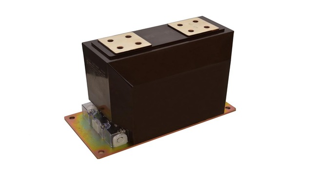
CHINT’s cast-resin instrument-transformer page describes indoor current and voltage transformers for metering, monitoring, and relay protection in 50 Hz or 60 Hz power systems. The page describes that range as fully enclosed with epoxy-resin insulation. Those statements apply to the listed product family; they do not establish an outdoor rating or a universal rating for every model. Review the exact catalog entry before specifying a device.
For a separate example, CHINT identifies its JDCF-66~220 series as an oil-paper-insulated, fully sealed voltage transformer. This is a different construction and product family from the cast-resin indoor range. Compare the applicable model data, voltage level, insulation coordination, installation conditions, accuracy, and secondary requirements before using either family in a project. The cast-resin instrument transformer page and the JDCF voltage-transformer documentation provide model-specific examples. CHINT’s MV instrument-transformer catalog lists additional CT and VT models and their stated technical data; verify the exact model and revision against the project specification.
SAFE SECONDARY-CIRCUIT PRACTICE
CT secondary circuits need particular care during testing and maintenance. Never open-circuit the secondary of an energized CT. With the primary energized, opening the secondary can produce a hazardous voltage and damage insulation or connected equipment. The U.S. Bureau of Reclamation’s field instructions require CT secondaries to remain closed or be safely bridged during relevant work. Use approved shorting terminals or test blocks, follow site isolation procedures, and have qualified personnel perform the work.
VT secondary circuits have different risks and should be protected and handled according to the design and manufacturer’s instructions. Do not treat a CT and VT secondary as if their safe test procedures were interchangeable. Before testing either circuit, identify the transformer type, check the wiring diagram, and apply the approved work controls for that installation.
FREQUENTLY ASKED QUESTIONS
WHAT IS CT BURDEN?
Burden is the load connected to a transformer’s secondary circuit, including instruments, relays, leads, and terminals. The connected burden must remain within the value stated for the selected model and accuracy class.
WHAT IS A RESIDUAL-VOLTAGE WINDING USED FOR?
On a VT designed with that winding and connection, it can provide a signal representing residual or zero-sequence voltage for ground-fault detection. It is a specific design feature, not a function available on every voltage transformer.
WHY DO INSTRUMENT TRANSFORMERS HAVE POLARITY MARKS?
Polarity marks identify corresponding primary and secondary terminals and their relative direction. Correct polarity matters when signals from multiple phases are combined or when a metering or protection scheme depends on direction. Follow the transformer and system diagrams when connecting terminals.