

Introduction
An automatic capacitor bank may connect and disconnect several times a day as plant loads change. Every closing operation creates a short electrical transient. If the switching device is selected only by comparing its ordinary current rating with the bank’s steady-state current, the contactor can experience severe wear long before the capacitors reach their expected service life.
The reason is the capacitor’s behavior at energization. An uncharged capacitor initially presents a low impedance, so current rises sharply as it charges. When a new step is connected beside capacitors that are already energized, the discharge path between stages can make the transient more demanding still. A dedicated capacitor switching contactor addresses this duty with a purpose-designed contact arrangement and pre-charge path. It is a specific control component in the compensation system, not a substitute for correctly sized fuses, a controller or a discharge circuit.
Why Capacitor Switching Creates a Different Duty
A motor contactor is selected for repeated switching of an inductive load. A capacitor bank is predominantly capacitive. At the instant of closing, the transient current depends on factors such as supply voltage, residual voltage on the capacitor, network impedance, the size of the connected bank and whether other stages are already energized.
The practical consequence is that the current at the switching instant can be many times higher than the bank’s normal operating current. In a multi-step automatic system, a contactor may also be asked to make frequent operations as the controller follows changing reactive demand. Contact erosion, overheating, welded poles and nuisance operation can follow when the device’s utilization category and switching duty do not fit the application.
The IEC 60947-4-1 requirements for contactors and motor-starters include the AC-6b utilization category for capacitor-bank switching. That category gives engineers a more appropriate basis for evaluating a switching device than a general-purpose contactor rating alone. The bank itself is a separately specified component; the IEEE standard for shunt power capacitors addresses capacitor ratings, service conditions and testing. The system still needs a coordinated design: utilization category does not remove the need to verify the bank rating, the manufacturer’s application limits and the protective devices around it.
How a Capacitor Switching Contactor Limits Inrush
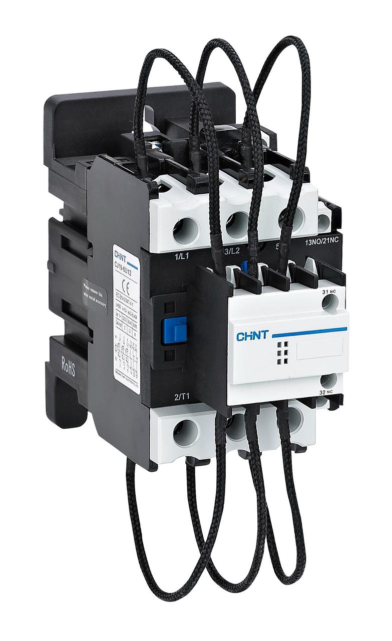
A dedicated capacitor switching contactor uses an auxiliary contact path and pre-charge resistors to connect the capacitor briefly before the main poles close. The resistors limit the initial surge; the main contacts then carry the capacitor’s normal operating current. This sequence reduces electrical stress at the main contacts and limits the transient imposed on the capacitor bank and upstream network.
The details matter. Pre-charge components must be matched to the contactor design and used as specified. Replacing a capacitor duty device with an ordinary contactor, or bypassing its resistor path, removes the feature that manages the first instant of energization. Nor should an engineer treat a stated inrush multiple as a universal allowance: the permissible current and capacitor capacity depend on the exact model, voltage and wiring conditions.
CHINT’s CJ19 capacitor switching contactor uses a resistor pre-charge circuit and is designated for AC-6b capacitor switching. The published series information lists operating voltages up to 690 V and model-dependent capacitor capacities. Those ratings are selection inputs—not a replacement for checking the specific model against the bank’s rated voltage, kvar, frequency and operating profile.

Match the Contactor to the Bank and Switching Pattern
Begin with the bank’s nameplate and the compensation panel drawing. Confirm the system voltage and frequency, each step’s kvar rating, the number of stages, the control-coil voltage and the expected switching frequency. Use the manufacturer’s capacitor-duty table for the actual network voltage; do not infer a suitable contactor size from a generic motor current chart.
Then consider the operating environment. A plant with variable-speed drives, welders or other nonlinear loads may have harmonic currents that increase capacitor heating and affect the overall compensation design. In those installations, harmonic assessment and any detuned reactor or filter requirements should be resolved with the capacitor bank design. A contactor does not correct resonance or excessive harmonic distortion.
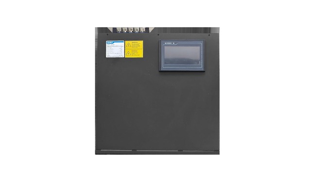
Finally, review the expected cycling. A contactor that is electrically suitable can still be a poor choice if the controller causes excessive switching, if the bank has not discharged before reclosing, or if the step size is too large for the load’s reactive-power profile. The CHINT capacitor cabinet solution illustrates how switching devices sit within a larger reactive-compensation arrangement. The contactor is one part of that design; the controller, capacitors, fuses, discharge components, ventilation and enclosure all affect service life and performance.
Coordinate Protection, Control and Maintenance
The contactor makes and breaks normal capacitor current. It is not a short-circuit protective device. Engineers should coordinate upstream fuses or breakers with the capacitor bank and contactor according to the equipment documentation and applicable installation rules. Control logic should also prevent rapid re-energization before stored charge has fallen to the permitted level. A discharge resistor or discharge device is normally part of the capacitor bank assembly; its rating and discharge time must follow the capacitor manufacturer’s instructions.
During commissioning, confirm coil voltage, terminal tightening, controller step order, phase connections, and the correct operation of each stage. Measure current per phase after the bank has stabilized and investigate unexpected imbalance, noise, heat or repeated contactor chatter. For maintenance, isolate the panel, verify absence of voltage and follow the site’s electrical-safety procedure before touching capacitor circuits. Visual checks for discolored terminals or damaged resistors are useful, but they do not replace testing by a qualified technician.
Where Dedicated Capacitor Contactors Fit
Dedicated devices are used in automatic power factor correction panels serving factories, commercial buildings and distribution systems with changing inductive loads. Typical loads include motors, pumps, compressors, HVAC equipment and production lines. The system may use several capacitor steps so that compensation can follow the operating load rather than remain fixed at one level.
The correct design objective is controlled switching with predictable component life, not simply achieving a target power factor at one operating point. The capacitor bank should be sized from measured or calculated demand; the controller should switch stages without unnecessary hunting; and the contactor should be selected for the bank’s electrical duty and expected operation count.
Five Checks Before Specifying a Capacitor Switching Contactor
- Confirm utilization category and rated capacitor capacity at the actual system voltage.
- Match coil voltage and control circuit requirements to the panel design.
- Check how the device handles inrush and whether pre-charge components are integral.
- Coordinate protective devices and capacitor discharge time with manufacturer data.
- Review harmonics, ambient temperature, enclosure conditions and switching frequency.
Conclusion
Capacitor banks place a short, high-stress demand on the switching device each time a step is energized. A dedicated capacitor switching contactor is designed for that duty, using a controlled pre-charge path and a capacitor-specific utilization category. Correct selection still depends on the complete panel: bank ratings, network conditions, controller settings, protection and maintenance access must all agree. CHINT’s CJ19 series provides a purpose-built option for low-voltage compensation systems, with model ratings that should be checked against the project’s actual operating conditions.
Frequently Asked Questions
Can a capacitor switching contactor replace the bank’s fuse or circuit breaker?
No. The contactor performs normal switching. Short-circuit and overcurrent protection must be provided and coordinated separately with the bank and installation.
Why can the contactor chatter when the automatic bank is operating?
Chatter can point to unstable control voltage, incorrect controller sensing, poor connections or switching logic that is reacting too quickly to changing load. Check the controller setup and circuit conditions before replacing components.
Does a capacitor bank need time to discharge before it is reconnected?
Yes. Residual charge can increase the closing transient. The permitted discharge interval depends on the capacitor bank and its discharge components; follow the manufacturer’s specified time and control interlock.
What maintenance evidence suggests that a contactor needs inspection?
Unusual buzzing, repeated switching, visible discoloration, damaged pre-charge components or inconsistent phase current are reasons for a qualified inspection. Always isolate and verify de-energization before work.