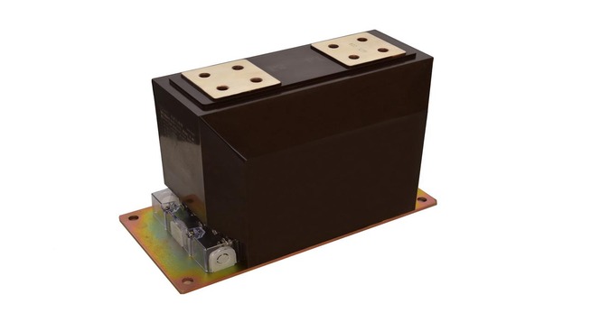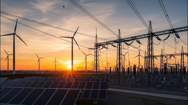


A long transmission line or cable has electrical capacitance. When the system is lightly loaded, its charging effect can contribute to a voltage rise, especially on long high-voltage circuits. A shunt reactor is connected in parallel with the network to absorb reactive power and help manage that condition. It is used in transmission systems, substations, and selected renewable-energy connections where the planned operating range calls for inductive compensation. Its rating and switching strategy must come from a system study; a reactor is not a general-purpose voltage regulator.
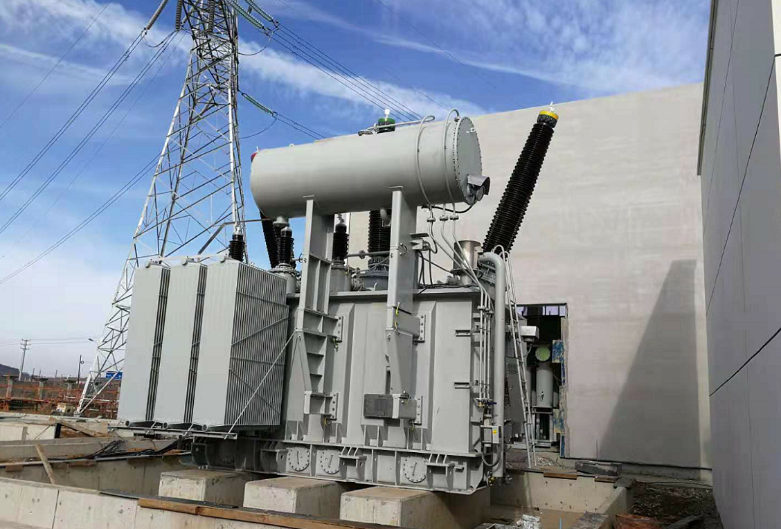
WHAT A SHUNT REACTOR DOES
A shunt reactor behaves as an inductive element. When connected in parallel with a line or bus, it draws magnetizing current and absorbs reactive power from the system. That inductive effect offsets part of the capacitive reactive power associated with a line or cable. The resulting voltage depends on the network’s resistance and reactance, generation, load, switching state, and other voltage-control equipment; the reactor does not set a fixed voltage by itself.
The connection is what distinguishes a shunt reactor from a series reactor. A shunt unit is connected in parallel with the circuit or bus according to the approved design. A series reactor is inserted in the current path and serves a different purpose, such as limiting current or controlling impedance. The distinction matters when reviewing a one-line diagram, protection scheme, and switching equipment. The equipment standard IEC 60076-6 covers shunt and series reactor types, while the relevant design and test requirements still depend on the selected reactor construction.
A shunt reactor also differs from a power transformer. Both use magnetic circuits, but a reactor is designed to absorb reactive power rather than transfer useful active power between voltage levels. It should therefore be specified from the power-system duty and operating profile, not selected as a substitute for a transformer, capacitor bank, or dynamic voltage-control system.
WHEN TRANSMISSION LINES NEED REACTIVE COMPENSATION
The need is often most visible on long overhead lines or underground cables at light load. A line’s distributed capacitance generates charging reactive power even when the transferred active power is low. If the network cannot absorb that reactive power locally, voltage at one or more buses can move above the planned operating range. A reactor can offset part of the charging effect and support the system operator’s voltage-control plan.
This is a system-level decision, not a rule that every long line needs the same reactor. Cable length, conductor and cable characteristics, voltage level, line energization conditions, load pattern, generation mix, and the other sources of reactive power all affect the result. A circuit that is heavily loaded at one time and lightly loaded at another may require a different operating approach across those conditions. Planners should assess both normal and contingency cases before fixing a rating or switching arrangement.
Renewable generation can add another operating pattern to the study. Wind and solar output vary, but variability alone does not establish a reactor requirement. The question is whether the combined network conditions create a reactive-power surplus or voltage issue that the proposed equipment is intended to address. CHINT lists transmission lines, cables, renewable generation, and substations among the application contexts for its shunt reactor range. The application should still be confirmed against project-specific load-flow and voltage studies.

CHOOSE THE CONNECTION POINT AND REACTOR DUTY
A reactor may be connected at a transmission-line terminal, a substation bus, or another point allowed by the network design. The connection point changes which part of the system it supports and how the reactor interacts with other sources of reactive power. A line-end connection can address charging on a particular circuit; a bus-connected unit may support several connected circuits. The choice should follow the utility’s operating plan, not a generic rule about where reactors belong.
Sizing begins with the line or cable electrical data, expected charging reactive power, system voltage range, load-flow cases, and switching or energization studies. Engineers also review acceptable voltage limits, contingency conditions, grounding arrangement, losses, sound limits, and site conditions. The selected Mvar duty must be evaluated across the relevant system states. Oversizing can create an undesirable voltage depression under other conditions, while undersizing may leave the original voltage issue unresolved.
A fixed reactor provides a defined inductive duty when it is in service. A variable shunt reactor can adjust its reactive output within the range and control method designed for that product. The two are not interchangeable choices by name alone: the project must define how quickly and over what range compensation needs to change, and verify that the proposed equipment and control scheme can meet those requirements. CHINT’s published case information describes a 400 kV, 200 Mvar variable shunt reactor project; it is an example of a project configuration, not a default rating for other networks. See the company’s variable shunt reactor project details.
REVIEW SWITCHING, PROTECTION, AND SITE CONDITIONS
A reactor specification should cover the required voltage and Mvar duty, insulation level, frequency, cooling method, installation environment, terminals, neutral arrangement, and accessories. The purchaser and manufacturer should confirm the exact values against the current data sheet and project documents. For example, CHINT’s product page lists several model ratings and cooling arrangements; those published options should not be read as a single combination available in every design.
Switching equipment deserves a dedicated review. Reactor switching can produce transient recovery voltage and other electrical stresses, so breaker selection and switching duty should be checked for the specific application. The IEEE guide to shunt reactor switching addresses breaker application and switching considerations. Protection functions likewise depend on construction and grounding: differential, earth-fault, overcurrent, temperature, and pressure-related protection may be relevant to particular designs, but no single scheme should be assumed for every reactor.
At the site, check clearances, foundation loading, lifting and access routes, ventilation, noise requirements, pollution, corrosion, altitude, and environmental conditions. Confirm how alarms and trips connect to the substation control system and how operators will decide when to switch the reactor. A factory test plan, commissioning checks, and maintenance instructions should be aligned with the approved equipment documents. CHINT’s substation solution provides broader context for the equipment and services that may be coordinated within a transmission project.
FREQUENTLY ASKED QUESTIONS
CAN A SHUNT REACTOR BE USED ON A MEDIUM-VOLTAGE NETWORK?
Yes. The technology can be applied at different voltage levels, but construction, connection, insulation requirements, and protection differ by application. Confirm that the exact product family and model are rated for the project; a high-voltage product page does not establish suitability for a medium-voltage installation.
WHAT DOES A SHUNT REACTOR’S MVAR RATING TELL A PLANNER?
It states the reactor’s nominal reactive-power absorption under its rated conditions. The amount absorbed in service depends on the applied voltage and the design. Use the nameplate and approved data sheet together with the system study when checking performance at actual operating voltage.
DOES A FIXED SHUNT REACTOR HAVE TO REMAIN ENERGIZED?
No. A fixed unit may be switched in or out according to the approved operating strategy and switching-duty review. “Fixed” describes its reactive-power characteristic while in service, not a requirement to keep it connected under every network condition.