Table of Contents |
Both contactors and relays may be best defined as electrically charged devices that are leveraged to manage and maintain the efficiency of the electrical circuit. Typically, the arc is defined by air contactors and a range of similar tools to support this purpose.
Because these switches are used in a single control panel, it often gets difficult to ascertain the difference between relay and contactor. So, what are the specific features of electrical contactors and relays? What is the working mechanism of contactor and relay? Well, we will find answers to these questions and more in the following few sections.
Introduction to Contactor and Relay
The distinctive feature of electrical contactors and relays is that they operate under the same principle. In the simplest terms, both the mentioned devices are solenoid switches that are further charged by electricity to tweak and manage the electrical load. Their construction is almost the same which further supports many similarities in their working principle.
So, how do contactors and relays operate and how are they made? Both these devices feature a top housing with a bunch of contacts. Note that these contacts are usually open, though they may also be found in a closed state. Unlike the top housing, the bottom part of the housing in both these devices features an excellent magnet and coil that goes on to maintain and protect the other tertiary accessories.
What Is the Key Difference Between Relay and Contactor?
Now that you have a clear insight into the working principle of relay and contactor, you might be wondering what the key difference in these devices are. The primary difference in both devices is in terms of the electrical current rating that they are built to sustain. Because contactors are leveraged to handle electrical loads with high voltage and current, they tend to have certain distinctive differences from the average relay.
For a more pertinent understanding of the difference between both devices, review the following feature definitions that summarize the device’s role and purpose.
Function
Control relay is best defined as a product that ensures that all the contacts in a specific circuit can be successfully operated even when the conditions alter in the same or similar circuits.
Contactors, on the other hand, are devices that are designed to interrupt an existing electrical circuit in a normal environment.
Size
The key difference in both the products is in their size. When compared to contactors, control relays have a fairly small size. Next, because of this small capacity, control relays carry less load than contactors.
Electrical Load and Circuit Range
While contactors are best suited to carry electrical loads that are higher than 10A, control relays can only carry electrical loads up to 10 A. That is also the reason, why you would typically find control relay systems being operated in single-phase circuit types, most predominantly the control circuits, whereas contactors can efficiently manage the three-phase electrical load.
Type of Contacts
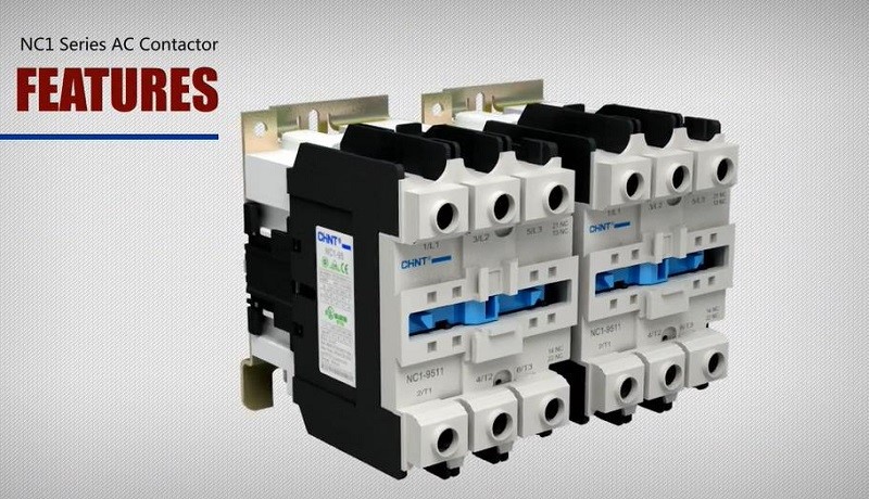
Another pertinent difference between relays and contactors lies in the devices’ auxiliary contacts. While you will find at least three power electrical contacts with some additional in-built contacts in a contactor, an average control relay will only contain two NO or NC type of electrical contacts. Again, while you will find control relays with both open and closed contacts, your typical contactor is tailored to operate only with open contacts. Unlike relays, they operate on Form A contacts.
System ratings
As mentioned earlier, the final and the biggest differences between the two devices lie in their system ratings and voltage control capacity. While conventional relays only have a 250 V rating, a contactor will usually have a rating of 1000 V or higher.
It is crucial to note that the biggest differences between the two devices are in their size and structural features. Relays are much smaller than contactors and that is why their function, voltage, and capacity are often limited when you compare them to a contactor. Since the devices are functionally different, you cannot use them interchangeably.
Applications of Relay and Contactors
As evident from their structure, both relay and contactor have specific functions. Relays, for instance, are designed to be leveraged in single-phase electrical circuits and they are best suited for single-phase applications. Alternatively, you might want to use a contactor in an electrical network with at least three phases. Even though the functions of the modern-day relay are varied owing to their multifaceted features, some of the basic applications include:
- Automotive devices
- Managing and monitoring motor
- Several industrial applications
- To manage and control electrical loads
As with relays, contactors come with a range of categories and although you will find them with several uses, the basic operation would include:
- To start motors
- To switch an existing electrical capacitor bank
- To control and monitor lighting fixtures
How to Choose a Contactor or a Relay?
If you are confused about choosing a contactor or a relay, you might want to consider the following couple of pointers:
Control relays are best suited for operations that involve single-phase circuits with a required electrical capacity of 250 VAC and a current capacity of 10 A or less.
Alternatively, you might want to use contactors when the current capacity is 9A or higher, in a single to a three-phase electrical circuit with an electrical capacity requirement of 1000 VAC or higher.
Once you consider these key factors, it will be easier to determine which device among the two is best suited to meet your requirements. As mentioned earlier, because both devices have specific and singular functions, it is best to use the appropriate product for the appropriate environment.
Summary
You would want to use a contactor to switch motor or lighting fixture or any other device that is known to drain high capacities of current. These devices also feature at least one specific pair of contacts in a three-phase input-output capacity. The contacts are open and, in some cases, categorized into more groups, namely the auxiliary contact with NO and NC capacity.
Relays, on the other hand, will feature only one or two pairs of open or closed contacts. You can choose to open or close the contact by simply tweaking the coil. Because both devices have distinctive functions, it is best to operate them only in their required capacity.




-metalclad-AC-enclosed-switchgear-banner.png)
