Transformers are indispensable electrical devices that transmit electrical energy between circuits by electromagnetic induction to modify voltage levels with little energy loss. Its efficiency centers around transformer design, including core material, winding topologies, and thermal management. That's why design criteria like flux density, insulation requirements, and load characteristics must be acknowledged. Remember, effective design decreases losses, increases reliability, and satisfies demanding performance benchmarks in many applications.
Basic Principles of Transformer Operation
Electromagnetic Induction in Transformer Design
Transformers work on Faraday's Law of electromagnetic induction. A time-varying magnetic flux is generated by alternating current in the primary coil. It links the secondary coil via a shared magnetic core. It induces a voltage proportional to the flux change rate. Notably, energy transfer efficiency depends on core high permeability and low hysteresis loss. For instance, grain-oriented silicon steel cores offer eddy currents. Diminishing leakage flux through core geometry optimization in transformer design keeps voltage regulation and efficiency.
Roles of Primary and Secondary Coils in Voltage Transformation
Input power for a magnetic field is proportional to the turns ratio, and input current goes to the primary coil. The secondary coil uses this field. Voltage output is scaled by turns ratio, Vs/Vp = Ns/Np. A transformer with 500 primary and 100 secondary turns gives a 5:1 voltage step-down. Coil insulation and spacing affect reliability at high voltages. In transformer design, winding alignment should lower parasitic capacitance. It boosts frequency response in RF transformers.
Type of Transformer
1. By Function
Ordinary transformers handle stepping up or down in utility grids. Special transformers are rectifier transformers for DC power supplies or furnace transformers in industrial heating. E.g., phase-shifting transformers manage power flow in interconnected networks. Transformer design needs customized core materials and insulation systems for working requirements.
2. By Phase
Single-phase transformers dominate residential applications. Three-phase transformers power industries and large grids for better efficiency and power delivery. Multi-phase transformers (6-phase or 12-phase) support high-capacity rectification in HVDC. Transformer design in multi-phase systems includes core shaping to adjust harmonics and magnetic flux distribution.
3. By Voltage Regulation Method
No-load transformers lack tap changers. It renders them simpler but less flexible for load variations. On-load tap-changing transformers adjust voltage under full load. For instance, substations may integrate vacuum or oil diverter switches for operation. The transformer design must accentuate lower arcing and better cooling for voltage adjustments.
4. By Winding Configuration
Dual-winding transformers are usual. Yet, triple-winding models may serve grid interconnection. Autotransformers use a single winding for primary and secondary for compactness. Multi-winding transformers in power plants manage multiple voltage outputs. The transformer design must meet winding insulation stress and short-circuit forces with thermal stability.
5. By Insulation and Cooling Method
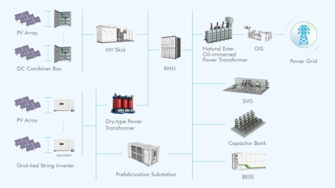
Oil-immersed transformers use mineral or synthetic oils for cooling and insulation. They suit high-power uses. Dry-type transformers use air cooling and epoxy resin insulation for buildings. Gas-insulated transformers (SF₆-based) are compact and handle desert or offshore platforms. The transformer design must optimize dielectric properties and heat dissipation for safety.
6. By Core Structure
Core-type transformers have windings encircling the core for high-voltage applications. Shell-type designs surround the windings with the core. It gives better mechanical support and lower losses. E.g., shell-type structures govern furnace transformers due to their fault tolerance. The transformer design should cut flux leakage and include core lamination techniques.
Key Parameters for the Design of Transformer
- Rated Voltage and Current: Transformer design demands the specification of rated voltage and current for operation under load. Voltage levels show the insulation class and material selection. Current influences conductor cross-section and cooling design. Underrating them risks overheating. Overrating increases costs unnecessarily.
- Rated Capacity: Rated capacity delineates the transformer's handling apparent power (kVA) without overheating or efficiency loss. Designers calculate rated capacity using the maximum expected load and load diversity. Over-designing rated capacity may cut efficiency at lower loads. That's why optimization is key to lifecycle cost.
- Losses in Transformers: Transformer design should decrease core and copper losses. Core losses depend on material and frequency, and copper losses count on winding resistance. Choose between premium core materials and conductor size for efficiency.
- Short-Circuit Voltage: Short-circuit voltage (percentage of rated voltage) is critical for fault tolerance and system stability. It affects leakage reactance and voltage regulation. Designers must confirm that it supports network impedance and fault-level requirements.
- Temperature Rise: Temperature rise is the allowed winding or core temperature increase under load. Transformer design cooling gets better using thermal modeling. Controlling such factors boosts insulation durability and thermal class compliance.
Conclusion
By learning about key principles and parameters, businesses and consumers can make informed decisions when choosing a transformer. In this field, adopting effective design, the CHINT power transformer is equipped with a smart grid. With environmental protection, friendly, intelligent, low partial discharge, safe and reliable characteristics, it fully meets the requirements of users.