Introduction
A protocol gateway plays a vital role in industrial and commercial systems. It helps transmit data from your equipment to your chosen cloud platform for monitoring and control. The CHINT SMG-WSR and SMG-ESR Open Protocol Gateways are designed for this task. They collect data from Modbus RTU devices and send it to your MQTT server in JSON format.
These gateways are not built for home or consumer systems. They support facilities, manufacturing lines, and infrastructure sites that need reliable data collection and remote management. This guide will walk you through preparing, wiring, configuring, and testing your protocol gateway so you can keep your systems connected and monitored at all times.
Understanding the CHINT SMG-WSR and SMG-ESR Protocol Gateway
The CHINT SMG-WSR and SMG-ESR gateways are versatile solutions for sending equipment data to a cloud platform, enabling remote monitoring of energy use, system performance, and alarms. They are suitable for a wide range of scenarios—including commercial, residential, data center, and industrial—where a customer or integrator can provide a compatible MQTT software platform.
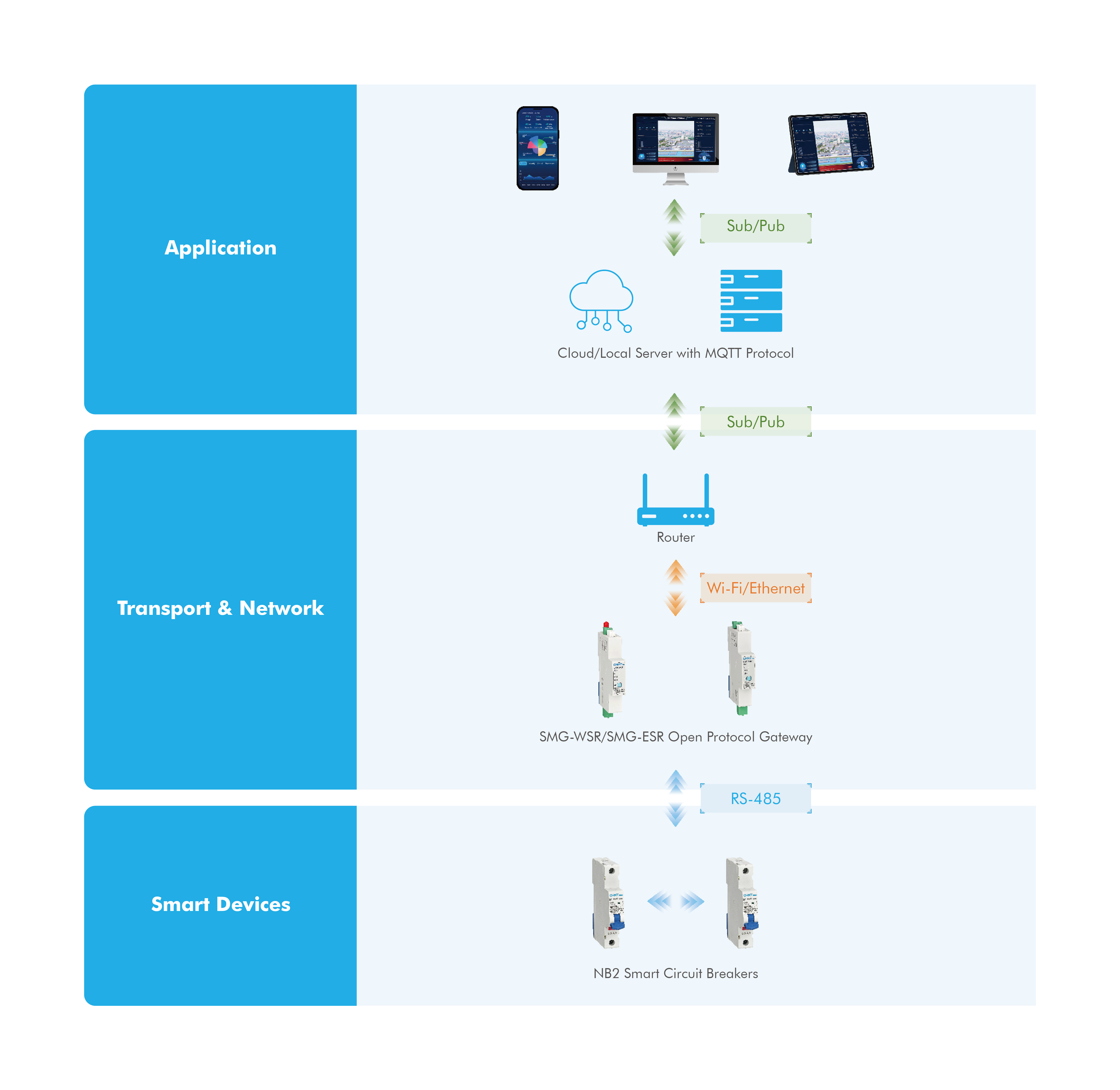
The protocol gateway converts data from Modbus RTU devices into MQTT JSON format. This means it takes data from smart circuit breakers and sends it to your MQTT server in a structured way your cloud platform can read. The SMG-WSR connects upstream to your platform using Wi-Fi, while the SMG-ESR connects using Ethernet. Downstream, both gateways use the RS-485 (Modbus RTU)connection to link with smart devices, including CHINT NB2 smart circuit breakers.
The gateways use a simple, open protocol. This helps reduce integration challenges when adding them to your monitoring platform.
Preparing Hardware for Your Protocol Gateway Setup
Before starting the installation, gather all hardware and check your network requirements. Having the correct hardware and a stable network will help your setup run smoothly. The CHINT SMG-WSR and SMG-ESR gateways need proper power, Wi-Fi or Ethernet, and clear workspace for DIN rail mounting. These gateways collect data from Modbus RTU devices and send it to your MQTT server. Completing these preparations will help avoid delays and wiring mistakes during your project.
Device Type |
Product Model |
Quantity |
Function |
Open protocol gateway |
SMG-WSR/SMG-ESR |
1 piece |
Data transmission and protocol conversion |
Power supply unit |
PSU-3 |
1 piece |
Supplies DC12V power to the gateway or NB2-40ZT 1P |
Smart circuit breaker |
NB2-ZT/NB2LE-ZT |
≥1 piece |
Collects electrical data, uploads to the platform, receives instructions |
Network device |
- |
As needed |
Provides network access for configuration, Wi-Fi hotspot or router |
Personal computer/laptop |
- |
As needed |
Accesses the gateway configuration web page |
Server Requirements
Server Type |
Requirements |
Cloud-based or local server |
MQTT protocol v3.1.1 or higher required |
Hardware Installation and Wiring
a. Installation
• Install the SMG-WSR/SMG-ESR gateway, PSU-3 power supply unit, and NB2 smart circuit breakers on the modular DIN rail. Here we use the SMG-WSR as an example.
b. Wiring between SMG and PSU-3
• Connect the main power line (L/N) to the input port at the top of the PSU-3.
• Connect the OUT1 port at the bottom of the PSU-3 with the power input port of the SMG, which is also located at the bottom. Pay attention to polarity (+ and -).
c. Wiring between NB2 and SMG
• Use the red communication cable provided in the package to connect NB2 to the SMG.
• For multiple cascaded NB2 circuit breakers, utilize the adaptors included in the package.
• The NB2-40ZT 1P is only available by powering from PSU-3. Connect the OUT2 port on the top of the PSU-3 to the communication port of the NB2-40ZT 1P.
d. Wiring of Network Cable
• For the SMG-WSR gateway, install the Wi-Fi antenna included in the package. For the SMG-ESR gateway, connect it to the network via an Ethernet cable.
e. Power On
• After completing the wiring, turn on the power, the indicator lights of the SMG, PSU-3, and NB2 should illuminate.
Gateway Configuration
1. Checking the indicator status
Check the gateway's indicator light flashing mode. When the gateway is a new one from the factory, the red indicator light will be in configuration mode with fast flash.
Refer to the checking table below for details.
Description of Indicator status |
||
Indicator Name |
Function |
Status |
Work-red light |
System operation status indicator |
Slow flashing in normal mode Fast flashing in configuration mode |
loT-Blue Light |
Network status indicator |
Super-fast flashing in network connection Fast flashing when the network connection is successful Slow flashing when Cloud MQTT connection is successful |
COM1 |
COM1 communication indicator |
Two tone LED: Blue when sending data Yellow when receiving data |
COM2 |
COM2 communication indicator |
Reserved
|
Explanation of Flashing Frequency |
||
Definition |
Frequency |
On-off Cycle |
Slow Flash |
0.5Hz |
1000ms on, 1000ms off |
Fast flash |
2Hz |
250ms on, 250ms off |
Super-fast flash |
5Hz |
100ms on, 100ms off |
Operation of Multi-function Keys |
||
Operation |
Function |
Notes |
Press for 1 second |
Switch between normal mode and configuration mode |
- |
Press for 7 seconds |
Reboot |
Press and hold for 7 seconds until the Working LED, loT yellow LED, and loT blue LED are all on, which means that the gateway has started to reboot. The reboot will be completed in about 5 seconds. |
Press for 15 seconds |
Reset |
Press and hold for 15 seconds until the Work LED, loT yellow LED, and loT blue LED are all super-fast flashing, which means that the gateway has started to reset.
Caution: Resetting will erase all prior settings. Once initiated, this action cannot be undone. |
2. Connecting to the Gateway Hotspot
When the SMG-WSR/SMG-ESR gateway is in configuration mode, it will broadcast a hotspot named "SMG-OPEN-XXXX". Please connect to this hotspot using your personal computer or laptop.
If your gateway is SMG-WSR, ensure the Wi-Fi antenna is located near the gateway to guarantee signal transmission.
3. Accessing the Gateway Configuration Web Page
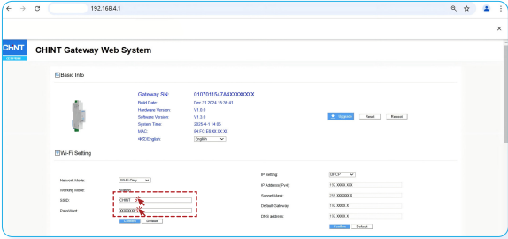
Once the PC/laptop is connected to the gateway hotspot, enter 192.168.4.1 in the browser, you will see the gateway configuration web page. Please record the gateway's SN information (e.g., "0107011547A4xxxxxxxx")
4. Configuring Network
If your gateway is SMG-WSR, enter your Wi-Fi name and password in the Wi-Fi settings section, then click the Confirm button. If your gateway is SMG-ESR, you can skip this part.
5. Configuring Server Information
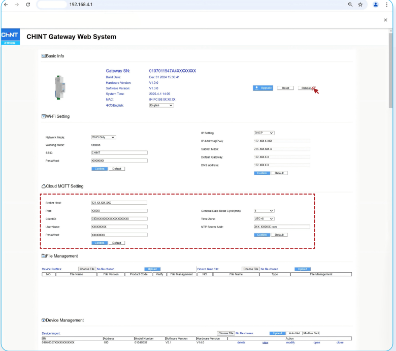
After the network configuration is completed, the WORK light of the gateway flashes according to configuration mode. Enter your server information in the Cloud MQTT Setting section, then click the Confirm button.
Once you see the pop-up message shows the configuration setting has been saved, please click the Reboot button in the upper right
corner of this page to take effect.
6. Auto-Networking with NB2 Smart Circuit Breaker
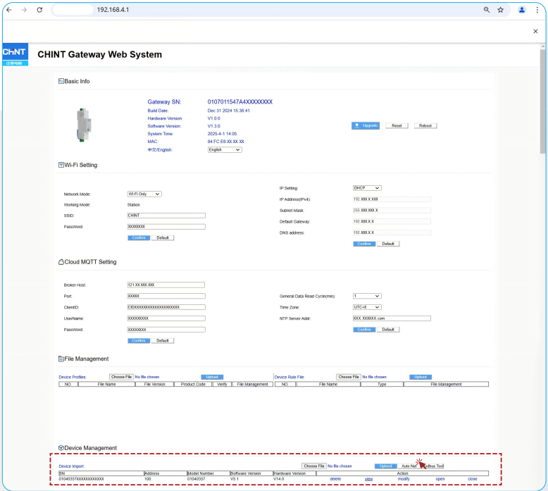
Make sure that NB2 has been wired to the gateway and the power is turned on. Click the Auto Net button in the Device Management section to initiate the networking process. After networking is completed, the gateway will automatically reboot.
After rebooting, press the gateway key to switch it to configuration mode. Connect to gateway hotspot and re-enter the configuration web page, check the NB2 information, such as quantity, SN codes and communication address.
When the gateway is connected to the cloud MQTT properly, the WORK light will flash according to normal mode, and the IoT light will flash at the same frequency. Once you see the pop-up message shows the configuration setting has been saved, please click the reboot button in the upper right corner of this page to take effect.
Platform Testing After Configuration
1. Connecting via MQTT Client
Use an MQTT client to connect to the MQTT server and subscribe to the relevant topics of the gateway. By default, the gateway reports data every 5 minutes. For specific MQTT protocol details, please refer to the additional MQTT communication table.
2. Testing on Your Platform
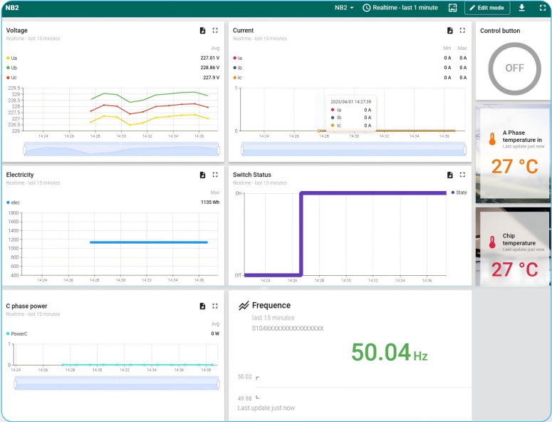
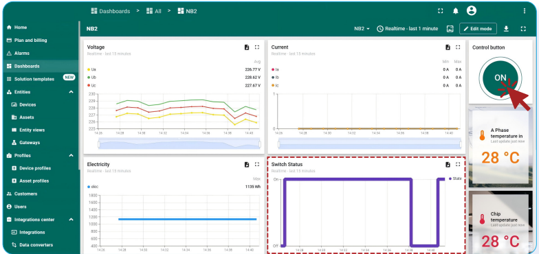
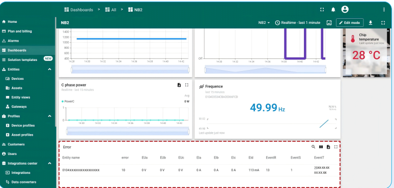
Here we tested some functions of the SMG-WSR/SMG-ESR gateway and NB2 smart circuit breaker using an open-source platform as a reference.
• Data Collection
The gateway collects various electrical parameters such as voltage, current, and energy data from NB2 devices.
• Remote Control
Remotely turn on or turn off of NB2 circuit breakers via the platform.
• Fault Alarm
The system triggers fault alarms when abnormalities are detected in the connected devices or the power system. Here we pressed the leakage test button of NB2, triggering leakage protection.
Conclusion
Configuring your CHINT SMG-WSR or SMG-ESR gateway is the key to unlocking a powerful, data-driven environment. After the initial setup, you gain the ability to monitor system performance in real time, analyze energy consumption, and manage all connected assets remotely.
Ultimately, this provides a steady stream of reliable data, empowering you to make smarter decisions, optimize efficiency, and manage your entire ecosystem—from a residence or data center to a large-scale industrial plant—with complete confidence.


