Motor overload is a common occurrence often seen in industrial automation. It refers to a motor drawing more current than it’s designed to handle. It can damage the electric motor or even cause fires. Thermal overload relays protect motors from these dangerous situations. This guide explores what causes motor overload, how thermal relays work, and when to use them.
Causes of Motor Overload
Motors can overload for many reasons. Some of the primary causes include:
1. Excessive Load on the Motor
Electric motors are designed to handle specific load capacities. When the load increases—such as processing materials that are too thick or dense—the motor must draw more current to maintain its speed. This elevated current generates excess heat in the motor windings.
2. Shaft Misalignment
Shaft misalignment causes increased friction between the motor and connected equipment. As a result, the motor has to work harder to overcome this resistance, which leads to higher current draw and heat buildup.
3. Worn Bearings
Bearings help reduce friction in rotating parts. Over time, they can wear out due to age, contamination, or lack of lubrication. Worn bearings increase resistance, causing the motor to draw more current and potentially overheat. Unusual noise is often an early sign of bearing wear and impending overload.
4. Phase Loss
Phase loss happens when one phase of three-phase power is lost. The motor continues to run on the remaining two phases, but this imbalance causes the remaining phases to carry more current. This quickly overheats the motor windings.
Parts of a Thermal Overload Relay
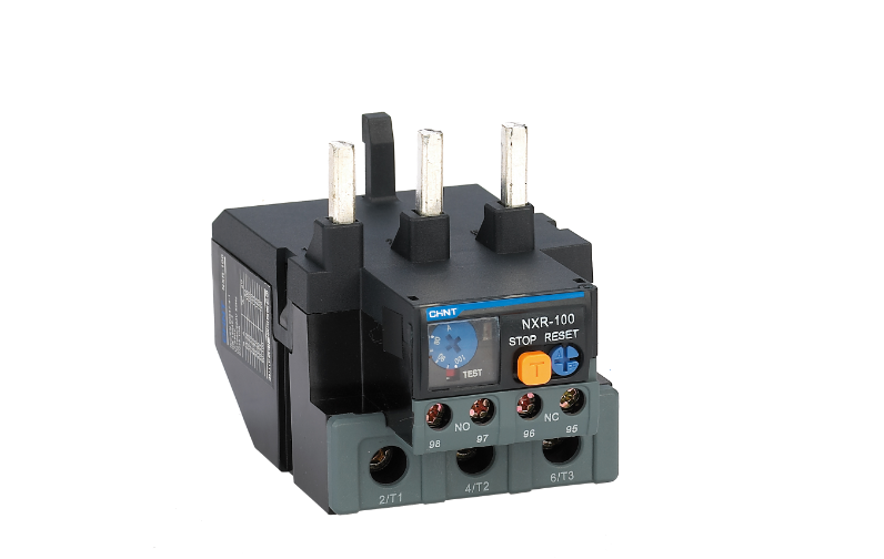
Thermal overload relays contain several important components. Together they create a reliable protection system.
1. Setting Switch
The setting switch adjusts the relay’s trip current and should be set according to the motor’s full-load amperage. Accurate setting is essential: if set too high, the motor won’t be adequately protected; if set too low, it may cause unnecessary or nuisance tripping.
2. Test Button
The test button manually trips the thermal overload relay. It simulates an overload condition. Regular testing ensures the relay will work when needed.
3. Stop Button
This button interrupts the control circuit which connects to the contactor. It provides a way to manually stop the motor. It’s particularly useful during maintenance or emergencies.
4. Reset Button
This restores operation after a trip. Some thermal overload relay devices reset automatically. Others need manual resets.
5. Main Contacts
Main contacts carry motor current. They open during an overload. This cuts power to the motor contactor. They must be sized for the motor’s current.
6. Auxiliary Contacts
These contacts are for signaling. They don’t carry the main motor current. They connect to alarms or control circuits. They change state when the thermal overload relay trips.
How a Thermal Overload Relay Works
Thermal overload relays operate on a simple principle. They detect excessive current through heat generation. This heat causes mechanical movement that trips the relay.
Take the bimetallic thermal relay for example.
It contains a bimetallic strip. The strip consists of two different metals bonded together. Current flowing through heating elements warms this strip. The bimetallic overload relay permits harmless momentary overloads. This includes the inrush current when starting the motor.
However, when there is a continuous excessive current draw, the strip deforms. This happens because the two metals expand at different rates when heated. The deformation trips the bimetallic overload relay. This causes the normally open (NO) contact to close and the normally closed (NC) contact to open.
Since the NC contact connects to the contactor control circuit, the circuit opens. This de-energizes the contactor coil. The contactor power circuit then opens and stops the motor. This entire sequence happens automatically when an overload condition occurs.
A Circuit Breaker is Necessary
3 phase overload relays protect against overloads, not short circuits. They respond too slowly to prevent damage from short circuits. Therefore, a circuit breaker or fuses must be installed for short circuit protection. The circuit breaker reacts instantly to dangerous current spikes. Both devices work together to provide complete motor protection.
When to Use a Thermal Overload Relay
Thermal overload relays are essential for motor protection. Circuit breakers alone aren’t enough. They can’t detect the gradual overheating that damages motors. Thermal overload relay devices sense small but persistent overloads. They protect against locked rotors, phase loss, and excessive load.
Conclusion
Overall, thermal overload relays are vital components in motor protection systems. They detect overload conditions that could damage motors. The relay trips when excessive current persists for too long. Understanding the causes of overload and how relays work helps maintain reliable motor operation.
At CHINT, we offer many products in this category. Our NXR Thermal Overload Relay series protects AC motors up to 690V. It features temperature compensation and multiple reset options. The NXR-38 works with contactors or as a standalone unit. All our products comply with international standards. Explore our complete range of motor protection solutions now.




-metalclad-AC-enclosed-switchgear-banner.png)
