Table of Contents |
A variable frequency drive is a type of motor drives that control motor speed and torque by varying the frequency of supplied current to electric motors. As straightforward as it may sound, the process involves a series of steps, including rectification, filtration, and inversion. This article focuses on the workings of VFD, mainly discussing how it controls the speed of 3-phase electric motors.
VFD Circuit Diagram Example
Before we explain the workings of variable speed drive, let’s go through the following VFD circuit diagram that visualizes the main components of variable frequency drive. This can help better understand how a variable frequency drive works:

How Does a Variable Frequency Drive Work?
It is noticeable that the 3-phase alternating current flows through a rectifier (converter), a filter, and an inverter in sequence before entering the electric motor:
Rectification
The VFD’s journey begins with the rectifier, where the 3-phase alternating current is converted into direct current. A typical rectifier is a six-pulse rectifier that consists of 6 diodes. Each diode has an anode and a cathode. Electrical currents can only go from anodes to cathodes and there will only be electrical currents if the voltage at the anode is greater than the cathode.
As we know, 3-phase AC provides three alternating currents on separate conductors. These currents fluctuate independently in their cycles of increase and decrease. When we connect 3-phase AC to the converter, only 2 diodes should be open at the same time, allowing only 1 current flow. As a result, the AC is rectified and converted into ripple DC.
Filtration
Next, the rectified current flows through the filter/DC bus. The DC bus is used to smooth the ripple in DC. This is done through capacitors and resistors. Although the DC bus is only represented by only 1 capacitor and 1 resistor, there are actually various capacitors and resistors associated in series and in parallel. The resistors are used to divide voltage and guarantee that all capacitors have the same voltage. The capacitors will absorb electrons when there is excess and will inject when there is a reduction. This helps smooth the ripples in DC.
Inversion
This step converts the DC into AC as a pulse width modulated output through an inverter. An inverter is basically a number of IGBTs (insulated gate bipolar transistors), which can be seen as switches that can turn on/off several thousand times per sec. The IGBTs open and close in pairs, i.e., the current can flow from phase 1 to 2, phase 1 to 3, phase 2 to 3, phase 2 to 1, phase 3 to 1, and phase 3 to 2.
In the oscilloscope, the waveform will look like 3-phase AC, but it will be a bit square and not applicable to electric motors. The IGBTs can close and open at different speeds and durations to change the waveform. This is called pulse width modulation, which helps mimic a sine wave and AC more suitable for electric motors.
Speed Control
The speed or revolutions per minute of the electric motor is related to the frequency of the inverted AC (speed equals frequency divided by poles and times 120). The higher the frequency, the faster the electric motor speed. VFDs can adjust the switching of IGBTs and change the waveform. By controlling the frequency, a VFD facilitates the variable speed control for electric motors.
Conclusion
Overall, a variable frequency drive (VFD) is a type of motor control device that effectively manages motor speed and torque. Through a sequence of stages including rectification, filtration, and inversion, the VFD converts incoming 3-phase AC into a controlled AC output that can vary in frequency and voltage. This capability enables precise adjustment of motor speed, crucial for optimizing efficiency and performance in various industrial and commercial applications.
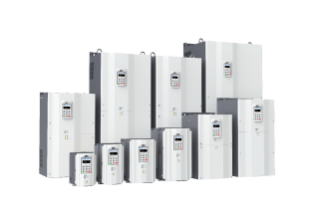
As a leading manufacturer, CHINT provides reliable VFD models. The NVF7 series drive is a top option. It adopts open-loop and closed-loop magnetic flux vector control technology, with fast load response, large low-frequency torque, strong overload capacity, etc., to achieve accurate control of the equipment. With stable output, torque limit, speed tracking, simple PLC, process PID and other application functions, it can meet the electrical drive needs of both constant torque type and heavy loads and variable torque and light loads. Visit our website to find out more about CHINT VFD.
If you have any questions or need further assistance, don't hesitate to reach out to us.