Table of Contents |
The current transformer and potential transformer (also called voltage transformer) are both measuring devices. A CT lowers the current signals for measurement purposes, while a PT lowers high voltage values into lower ones. The transformers are designed to measure whether power systems are both accurate and safe.
In addition, the CT and PT transformer reduces the current and voltage from high to low value. The current transformer and voltage transformer have similar construction since they feature a magnetic circuit in their primary and secondary winding.
Regardless, they have distinct differences. This post breaks down the current transformer vs. potential transformer and highlights the differences between the two.
What Is Current Transformer and Potential Transformer
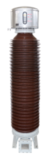
Current transformer
Also known as CTs, current transformers are devices that measure alternating current. They are widely used to measure high magnitude currents.
A current transformer essentially lowers (steps down) a high current to a lower, safer level that you can manage properly. It steps down the current to be measured so that you can measure it with an average range ammeter.
Functions of a current transformer include:
- Converting large primary currents into small 1A/5A current
- Providing the current for the coil of measuring device and protective relaying
- It separates primary voltage from secondary voltage.
Characteristics of a current transformer include:
- The resistance of the instrument’s current coil with which the CT’s secondary winding is connected is small. The CT transformer operates under a state close to the short circuit under normal condition
- The primary winding is installed in series in the current.
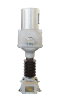
Potential Transformers
On the other hand, potential transformers, also known as voltage transformers, measure an aspect of the power supply. While a current transformer measures current, the potential transformer measures voltage.
The majority of American homes use different voltages for various purposes.
Functions of the potential (voltage) transformers include:
- It measures and reduces high voltage values into lesser values
- Voltage transformers proportionally convert the high voltage into a standard secondary voltage of 100V or lower for easier utilization of protective and measuring instruments/devices
- To isolate the high voltage from electricians using the PT.

Difference Between Current Transformers and Potential Transformers
Function
One of the major differences between CT and PT transformers is their functions.
On the one hand, a current transformer reduces a high current to a safer and more manageable level that you can measure. It converts large primary currents into small 1A/5A currents that can be measured on the ammeter.
On the other hand, a potential (voltage transformer) measures and reduces high voltage values into lesser values. It converts the high voltage into a standard secondary voltage of 100V or lower.
Types
The current transformer is divided into two types, including wound and closed core. The potential transformer is also divided into two categories(types), including electromagnetic and capacitor voltage.
Connection
In the current transformer, the primary winding is connected in series to the transmission line whose current is to be measured, and full line current flows via the winding. On the other hand, the potential transformer is connected in parallel with the circuit, meaning full line voltage appears across the winding.

Transformation Ratio
The transformation ratio in a current transformer is high, while in the potential transformer, the ratio is low.
Primary and Secondary Winding
In a current transformer, the primary winding has a smaller number of turns and carries the current to be measured. In potential transformers, the primary winding has many turns and carries the voltage to be measured.
In a current transformer, the secondary winding possesses large numbers of turns on the secondary side and is connected to the current winding of the instrument. In a potential transformer, the secondary winding has a small number of turns on the secondary side and is connected to the meter or instrument.
Core
The current transformer is designed with silicon steel lamination, while a potential transformer is designed with top-quality steel operating at low flux densities.
Primary Current
In a current transformer, the primary current doesn’t depend upon secondary side circuit conditions. On the other hand, in the potential transformer, the primary current relies on secondary side circuit conditions.
Use
With a current transformer, you can use a 5 Ampere ammeter to measure high currents such as 200 amperes. On the other hand, with a potential transformer, you can use a 120V voltmeter to measure high voltages such as 11KV.
Secondary Side
In the current transformer, the secondary side cannot be open-circuited when under service. On the other hand, in a potential transformer, you can open-circuit the secondary side without any damage.
Input Value
In the current transformer, the input value is constant current, whereas, in a potential current, it is a constant voltage.
Secondary Winding Range
In a current transformer, the range is 1A or 5A, while in a potential transformer, it is 110V.
Burden
The current transformer doesn’t rely on the secondary burden, whereas the potential transformer depends on the secondary burden.
Applications
A current transformer has different applications, including measuring current and power, monitoring the power grid operation, and operating a protective overlay.
On the other hand, the potential transformer’s applications include power source, measurement, and operating protective overlay.
Generally, a current transformer’s secondary side allows a short circuit but no open circuit. On the other hand, a potential transformer’s secondary side allows an open circuit but no short circuit.
Conclusion
Ultimately, current transformer testing and potential transformer testing ensure that instrument transformers are working correctly. It also ensures voltage and current remain within their stipulated framework. The transformers ensure your electrical gadgets or home appliances are protected from sudden electrical problems.
Contact an electrical professional for more assistance and further information on the differences between current and voltage transformers.
If you have any questions or need further assistance, don't hesitate to reach out to us.