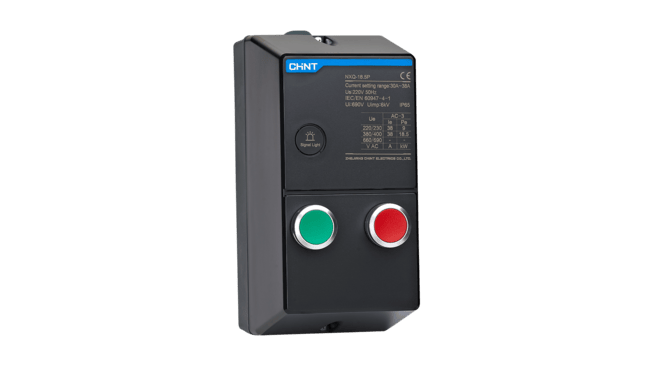


Introduction
A control relay is a small component with a large influence on how an industrial panel behaves. It lets a low-power control signal operate one or more contacts, helping a PLC, sensor, timer, or pushbutton command a circuit while keeping the control and switched sides electrically separated by the relay’s insulation system. A relay that is mismatched to the coil supply, contact load, or duty cycle can create intermittent faults that are difficult to trace.
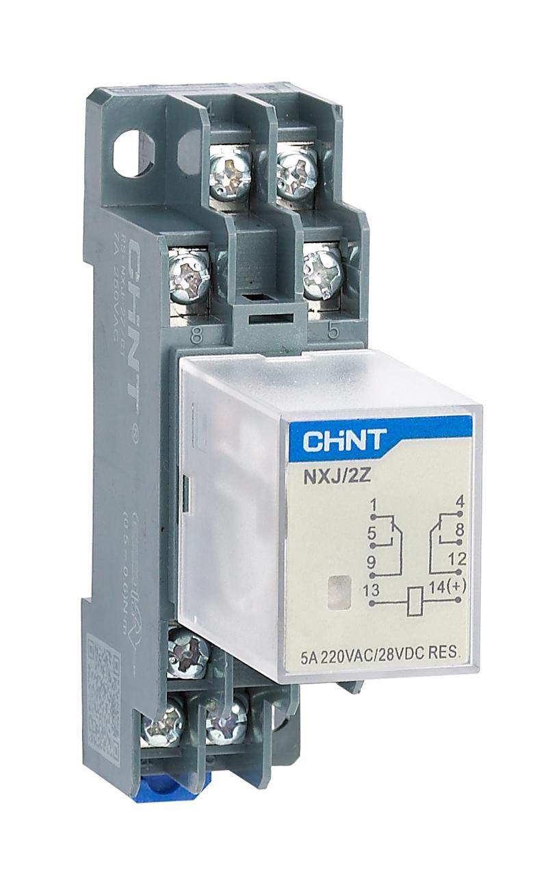
Selection begins with the circuit’s job, not the relay’s footprint. Identify what signal will energize the coil, what the contacts will switch, how often the operation occurs, and how the device must be mounted and maintained. CHINT’s NXJ plug-in relay and NJX12 miniature relay provide examples of general-purpose devices used in control panels and automation interfaces.
What a Control Relay Does in a Panel
When the coil receives its rated control voltage, the magnetic field moves the armature and changes the contact state. A normally open (NO) contact closes while the relay is energized; a normally closed (NC) contact opens. A changeover contact includes a common terminal that moves between the NC and NO paths. These contacts can provide interlocking, signal routing, status indication, alarm logic, or an interface between a controller output and a separate circuit.
A relay is not automatically a substitute for a motor starter or contactor. Small control relays are usually selected for control and signal loads; switching a motor or other high-inrush power load requires equipment specifically rated for that duty. Check the relay’s resistive, inductive, and lamp-load ratings, switching voltage, and utilization category where provided. A contact’s headline ampere rating cannot be applied indiscriminately to every load type.
Selection: Match the Coil, Contacts, and Installation
Start with the coil. Confirm AC or DC, nominal voltage, frequency for AC, available control-supply tolerance, and whether the PLC output can supply the relay’s pickup current. Coil voltage options vary by series. Never apply the contact rating as though it were a coil rating; the coil and switched circuit have different electrical limits. Where the control supply can rise or dip, compare pickup and drop-out thresholds with the actual supply range.
Next choose the contact configuration. SPDT (one changeover) can route one signal between two paths; DPDT provides two changeover poles; 3PDT or 4PDT designs give more independent contacts where the wiring and rating allow. CHINT describes NXJ models with 2Z, 3Z, and 4Z contact options, plus a 2ZH high-current version. The NJX12 product page lists 1Z, 2Z, and 4Z configurations. Confirm the exact model suffix and terminal layout before designing the panel.
Then verify the contact rating for the real load. Consider steady current, inrush, switching voltage, power factor, DC arc interruption, expected operation count, and electrical life. A relay that switches a small PLC input has a different duty from one switching a solenoid valve or lamp bank. If the load current or inrush exceeds the miniature relay’s rating, use an appropriately rated interposing relay, contactor, or solid-state device and coordinate its protection.
Finally review the panel constraints: socket and base, DIN-rail or PCB mounting, terminal accessibility, vibration, ambient temperature, enclosure ventilation, coil indicator, suppression accessory, and replacement strategy. Socket-mounted relays simplify replacement, while the base and retention hardware must be specified with the relay. Make sure the device’s insulation and pollution environment are appropriate for the panel.

Reading a Control Relay Wiring Diagram
A typical diagram separates the coil terminals—often marked A1 and A2—from the contact terminals, which may be labeled COM, NO, and NC or numbered according to the manufacturer’s scheme. Do not assume that two relays use the same pin layout. Use the product’s wiring diagram and socket markings, then confirm the coil and contact terminals with a continuity test while the relay is de-energized.
In a PLC interface circuit, the controller output energizes the relay coil; the relay contact then switches the field signal or load. Check whether the output is sourcing or sinking, whether it is transistor or relay type, and whether its rated current can drive the coil. Add an interposing relay when the PLC output’s voltage, current, isolation, or contact form does not suit the field circuit. Keep control and load conductors separated as required by the design and local electrical rules.
A DC coil can produce a voltage transient when it is switched off. Use a suppression device compatible with the coil and output device, observing polarity if a diode is used. Suppression can lengthen release time, so verify that it does not interfere with the required sequence. AC coils use different suppression methods. Follow the relay and controller instructions rather than adding an arbitrary component.
For stable connections, use the conductor type and gauge accepted by the socket, tighten terminals to the specified torque, label both ends of each wire, and protect exposed circuits during testing. Before energizing, check coil supply, fuse or breaker protection, terminal mapping, control logic, and the load’s compatibility with the contact rating.
Troubleshooting and Commissioning
If a relay does not pull in, measure the voltage directly across the coil while the command is active. Confirm that the output is switching, the common reference is correct, and the coil is the specified AC or DC version. A glowing LED indicates an indicator state, not necessarily that the contacts have the expected continuity.
If the relay chatters, inspect for low or unstable coil voltage, loose terminals, an incorrect AC frequency, a weak connection in the control circuit, or an output that cannot supply the coil current. If the relay operates but the load does not, test continuity across COM–NO or COM–NC in both energized and de-energized states, then trace the wiring downstream. Contacts that overheat or weld often point to excessive inrush, an unsuitable load category, or inadequate suppression.
During commissioning, verify each relay against the schematic and I/O list. Record the part number, coil rating, contact form, socket, protection accessory, and replacement equivalent. CHINT’s NXJ relay data and NJX12 relay data provide model-specific information; its NXJ installation guide also illustrates installation and verification steps. Use the current catalog and wiring diagram for the exact variant. The NJX12 series lists compliance with IEC/EN 61810; consult the IEC’s IEC 61810-1 standard page for the general requirements framework.
Conclusion
A reliable control relay installation depends on matching the coil to the control supply, contacts to the actual load, and mounting accessories to the panel design. Read the model-specific diagram, test the full circuit under its intended duty, and document the wiring and replacement parts. Those checks make relay selection predictable and reduce avoidable faults during commissioning.
Frequently Asked Questions
What is the difference between a control relay and a contactor?
A control relay is generally used for signal and control switching at its rated load. A contactor is designed for higher-power loads and more demanding switching duties, such as motors. The correct choice depends on the load category, inrush, voltage, and switching frequency rather than device size alone.
Can a PLC output drive a control relay coil directly?
Only when the PLC output type, voltage, and current capacity match the relay coil requirements. Check the output’s sourcing or sinking arrangement and transient protection before connecting the coil.
What does 2Z or 4Z mean on a relay?
In CHINT’s product naming, Z denotes a changeover contact set. For example, 2Z means two changeover contacts and 4Z means four. Confirm the specific product’s terminal diagram and rating because naming conventions and available forms can vary by series.
Why does a relay need a socket?
A socket provides the relay’s terminal interface and can make replacement easier without removing panel wiring. The socket must match the relay series and be mounted and wired according to the manufacturer’s diagram.
Should a relay coil have a fuse?
Overcurrent protection should follow the control-circuit design, conductor rating, applicable electrical code, and device instructions. A relay coil does not replace branch-circuit protection, and the required fuse or breaker rating depends on the circuit—not just the relay model.