Shunt capacitors are an integral part of a power system because it helps in power factor correction. The fact that this apparatus can be deployed anywhere in a circuit or a power network makes it the ideal option for this work. Shunt capacitors are also relatively cheaper than series capacitors and easy to install.
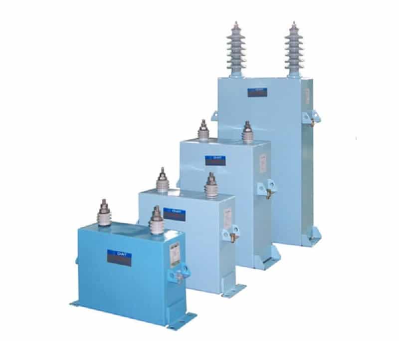
In a power distribution system, electrical engineers place a connector in parallel throughout the transmission. This gadget is known as a shunt capacitor. The shunt capacitor helps balance power transmission issues such as low voltage regulation, poor reliability, and power factors. Moreover, it can divide into HV capacitor and LV capacitor.
How Does a Shunt Capacitor Work?
A shunt capacitor has several functions which change from time to time depending on the application. However, it is useful in stabilizing power to avoid a lag between the voltage and current within a power system.
A lag between the voltage and current causes a decrease in the electrical power factor , which leads to an increase in the demand for more power from the source. In the long run, the cycle leads to power surges and loss of lines, also known as inductive reactance.
To counteract this flaw, engineers can introduce a capacitive reactance into the system. Using several units rather than one creates a reliable reactance against recurring inductive reactance. This group of capacitor units is referred to as a capacitor bank .
Capacitor banks are common within power substation or systems that supply energy to businesses and residents within a particular region. An improved voltage profile comes with a few perks that include:
- Ease in switching to a backup plan
- Extends the life of the equipment
- Reduces the need to add anything new into the system to balance power
In cases where the transmission powers over 69kV or more of energy, a capacitor bank speeds up the power transmission levels without adding a new line or larger conductors.
How Do You Connect a Shunt Capacitor?
You can connect a shunt capacitor in several locations. However, capacitors are frequently used in three key spots, which include:
- Electricity pole-mounted capacitors – These are usually mounted on electric poles either in fixed or switchable units. These variations are useful in meeting power loads between 460V – 33kV. Capacitor units mounted on poles usually range between 300 – 3000kVAR.
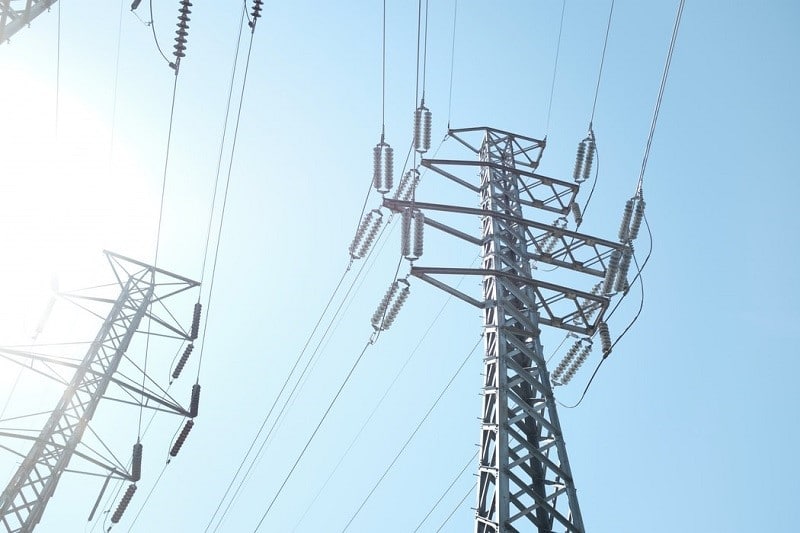
- EHV Shunt capacitor banks – Extra high voltage substations transmit power in bulk to load centers. When transmitting high-point loads of power, these lines tend to drop voltage significantly. As such, the EHV capacitors come into play when necessary, to create reactive power.
- Substation capacitor banks – These are installed in substations to operate voltages between 2.4 – 765 kV. The concerned parties take a critical look at the load flow and stability of the banks before installation.
Aside from these three locations, capacitors are also placed in other areas on a need basis. These can be connected in two ways, namely delta and star connection. In a star connection, the network is formed on three points that form a star shape.
More so, the interchangeable points of the cords are linked to one another. There is a neutral or star point within the connection and a line current that is equivalent to the phase current. Each curve receives up to 230V, and this connection is used mainly in transmission networks.
Delta connection uses a phase voltage equal to the line voltage, considering that it requires a large number of turns. Better yet, each series receives a maximum of 414V, and this connection is more prevalent in power distribution networks. Consequently, this connection requires high insulation to safeguard it from the adverse effects of high-power voltages.
Application of Shunt Capacitors
As mentioned above, shunt capacitors can be used in various locations, including electricity poles, substations, power transformers, EHV, and LV lines, among others. The application of shunt capacitors in utilities reduces the current flowing through the distribution feeder with the help of reactive power.
As such, it cuts down on the loss of lines and unnecessary use of power. Aside from redistribution of voltages, shunt capacitors also increase the transfer of power within the system without adding new lines or conductors to stabilize the connection.
Another critical role of a shunt capacitor is support. It holds together the transmission system voltage when there’s a peak extra-high voltage transmission, giving it ultimate access to the grid. Consequently, you don’t need to spend on upgrades whenever the system transfers a significant load of power.
And in this case, generators do not have to overwork to produce both reactive power and a real power. With lesser reactive power flowing through the lines, the lines have more capacity and less loss of systems.
What Is the Difference Between Series Capacitor and Shunt Capacitor
There are several differences between series and shunt capacitors; however, the most significant one is in the improvement of power load. Shunt capacitors help ease the lag between the current and voltage that occurs after an inductive load to the transmission line.
For this reason, this option is reliable when it comes to stabilizing the system, improving the power factor, and increasing the line voltage.
A series capacitor, on the other hand, is effective in reducing the power reactance. Unfortunately, voltage rise is only possible across terminals, unlike in shunt capacitors, allowing voltage rise in lines. More so, this connection does not affect the stability of the power grid or power factor.
Conclusion
All in all, shunt capacitors are also easy to install and maintain, and they have a longer life span than their counterparts. Therefore, they are a more preferred option when it comes to stabilizing power systems.


-metalclad-AC-enclosed-switchgear-banner.png)
