Table of Contents |
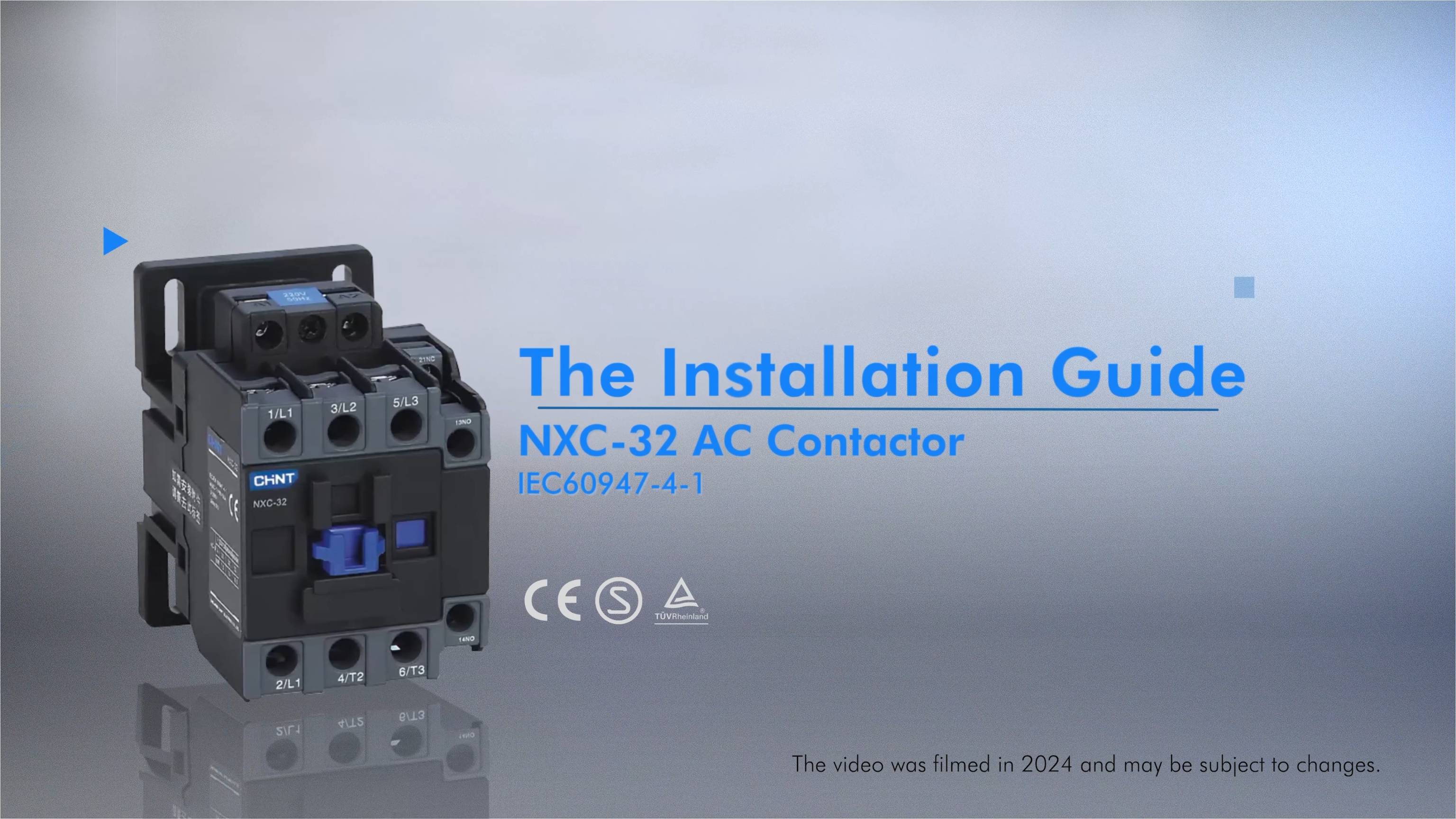
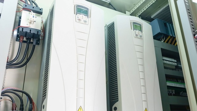
The CHINT NXC-32 AC contactor is an advanced electrical switching device. It’s designed for controlling electrical circuits in various industrial and commercial applicationsm, such as power distribution in HVAC systems. Apart from this, it’s also used in manufacturing equipment and complex electrical networks for the same purpose. This comprehensive guide presents the precise steps of installing this AC Contactor safely and effectively.
Preparation
Installing electrical equipment requires careful planning and attention to detail. Proper preparation is key. Follow these electrical safety guidelines:
1. Safety Precautions
Before starting, completely disconnect the power supply from the main electrical source. Also, wear appropriate personal protective equipment (PPE). This primarily includes insulated gloves and safety glasses.
2. Tools and Materials Needed
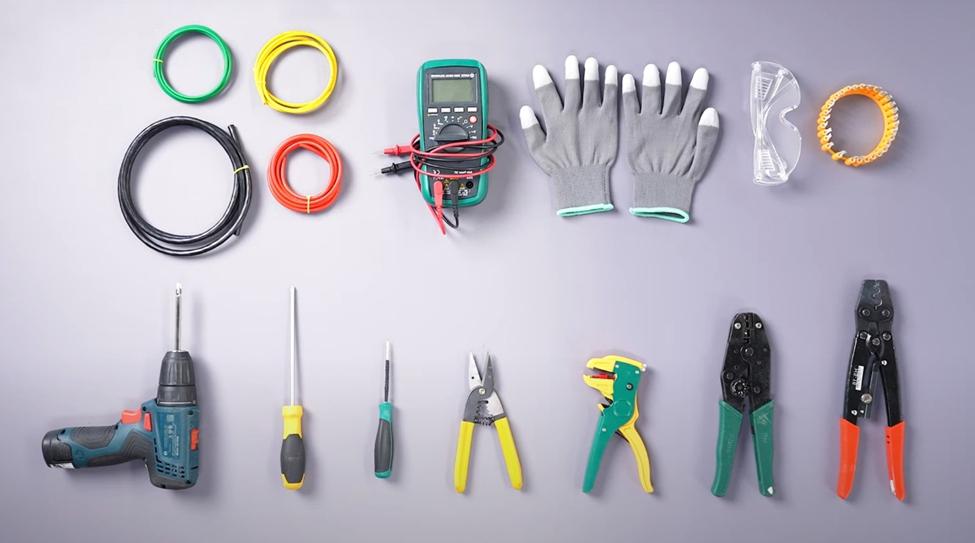
In addition to electrical safety guidelines, gathering proper contactor installation tools is essential. The required tools/materials include:
- Wire strippers for precise cable preparation
- Crimping tools for secure wire connections
- Screwdrivers with appropriate sizes
- Wire lugs for robust electrical connections
- Insulated gloves for personal protection
- Multimeter for electrical testing
- Appropriately sized copper wires
- Protective glasses for eye safety
Installation Steps
Proper installation of NXC-32 industrial contactors requires a methodical approach. Follow these steps:
1. Pre-Installation Checks
Before mounting the AC Contactor, conduct thorough preliminary assessments. This is to guarantee compatibility and appropriate contactor installation conditions:
- Verify the model matches the intended working conditions. Carefully compare the contactor’s specifications with your electrical system requirements.
- Select a suitable installation location. Ensure the mounting surface remains level, not tilted more than ±5° during operation.
2. Installing the Contactor
Precise installation techniques are critical for secure and reliable operation of these power distribution components:
- Align the contactor’s stopper with the top edge of the mounting rail, ensuring perfect positioning.
- Press down firmly to snap the contactor securely into place. You should hear a distinct clicking sound indicating proper installation.
- For removal, gently press at the bottom and tilt forward to detach the AC Contactor smoothly.
3. Wiring the Main Circuit
Accurate wiring is fundamental to the performance and safety of these power distribution components. Follow these guidelines:
Wire Selection
Select wires with cross-sectional areas appropriate for the product’s current rating. For the NXC-32 industrial contactors, it’s recommended to use wire cross-sections between 1.5-6 mm² (S(Cu)) for current ratings of 25, 32, and 38 amperes.
Stripping Insulation
Carefully strip insulation from main circuit, auxiliary, and coil circuit wires, exposing specific lengths of copper:
- Main Circuit Wires: Strip 11-13mm of insulation.
- Coil and Auxiliary Circuit Wires: Strip 9-11mm of insulation.
Crimping Wire Lugs
Use crimping tools to attach wire lugs, ensuring robust and reliable connections. Apply consistent pressure when crimping to create a mechanically and electrically sound connection between the wire and lug.
Terminal Mapping
Follow terminal mapping precisely when installing these power distribution components. Here are the recommendations to ensure you follow electrical safety guidelines:
- 1/L1, 3/L2, 5/L3 for main circuit input
- 2/T1, 4/T2, 6/T3 for main circuit output
- 21 and 22 for normally closed auxiliary contacts
- 13 and 14 for normally open auxiliary contacts
- A1 and A2 for coil terminals
4. Tightening the Screws
Use an electric screwdriver set to specified torque values. For M3.5 screws, use 1.2 N·m; for M4 screws, use 1.85 N·m to ensure secure connections.
For a more direct look into the installation process of the NXC-32 AC Contactor, check out our YouTube video:
Testing
Comprehensive AC Contactor testing validates the installation’s reliability and performance.
1. Pre-Power-Up Checks
Connect the coil to the rated control power supply with the main circuit uncharged. Conduct thorough operational testing before full system activation. This critical step helps identify potential contactor installation issues before putting the entire electrical system under load.
Verify the control voltage matches the contactor’s specifications. For the NXC-32 industrial contactors, typical control voltages range from 24V to 415V AC. Ensure you’re using the exact voltage rating specified on the contactor’s nameplate to prevent potential damage or malfunction.
2. Continuity Test
Use a multimeter to confirm normal AC Contactor operation after power-up. Pay special attention to contact resistance and switching performance. A typical good contactor should show minimal resistance and clean, crisp switching characteristics.
Troubleshooting Common Issues
Despite careful installation, occasional challenges may arise. The following are some common issues and their troubleshooting methods:
1. No power
Check wiring connections thoroughly. Potential causes include loose terminal screws, incorrect wire gauge, improper crimping of wire lugs, or disconnected control voltage. Verify all electrical connections are tight, correctly sized, and properly installed.
2. Unusual Noise
Inspect core and contacts carefully. Grinding, chattering, or excessive buzzing could indicate misalignment, accumulated debris, or mechanical wear. Check for:
- Foreign particles on the contactor’s pole faces
- Misaligned mounting
- Potential core or coil damage
- Signs of mechanical stress or uneven mounting
3. Blackened Contacts
Typically harmless and not affecting performance, these indicate minor electrical arcing during switching. No troubleshooting is needed since blackening is a normal consequence of electrical contact operation.
For complex issues and more in-depth troubleshooting, consult NXC-32 AC Contactor user manual or contact CHINT representatives.
Conclusion
Installing the NXC-32 AC contactor requires proper safety precautions and systematic execution. Carefully follow the outlined steps, i.e. preparation, installation, wiring, testing, and troubleshooting. With these guidelines, you can ensure reliable and efficient AC contactor performance. Visit our website to explore our extensive product range in the AC Contactor category.


