Introduction

How much energy could a home save if its electrical system was designed to guide power instead of simply deliver it? Most people assume efficiency starts with buying better appliances. It does not. The real gains happen earlier, during the planning stage when electricians decide where cables run, how loads get grouped, and what metering goes in. Those decisions shape consumption patterns for decades. This article looks at how final distribution boards, circuit layouts, and smart meters affect daily energy use in homes.
Energy-Efficient Homes Start With Electrical Installation Design
Efficiency gets baked into a building during design, not after. Where cables run, how circuits get grouped, and which loads share pathways all affect electrical losses before anyone plugs in an appliance. International standards like IEC 60364-8-1 now rank energy efficiency alongside safety and capacity as a core design priority. Voltage drop is one of the biggest culprits behind wasted power.
Undersized cables and unnecessarily long circuit runs force voltage losses that make connected equipment draw more current to compensate. When cables are undersized or circuits run longer than necessary, voltage loss increases. This forces connected equipment to draw more current to compensate. The result is higher consumption and reduced appliance lifespan.
Poor load distribution creates another problem. When heavy-use circuits share pathways with lighter loads, the entire system works harder than required. Circuit grouping based on usage patterns prevents this imbalance.
Buying an energy-rated refrigerator or LED bulbs will not fix a poorly wired house. If the foundation has problems, efficient appliances just mask them temporarily. Most homeowners underestimate how much the wiring itself contributes to their electricity bills. Builders and residents who understand home electrical basics tend to ask better questions and catch design flaws before they become permanent.
How Do Final Distribution Boards Shape Residential Power Efficiency?
Think of the distribution board as a traffic controller for electricity. It decides which circuits carry which loads, how those loads interact, and where power actually flows when someone flips a switch. Get the board layout right, and homeowners gain precise control over different areas and usage types. Get it wrong, and inefficiencies become permanent fixtures of the building.
Circuit Segmentation and Load Balancing
Splitting lighting, HVAC, sockets, and major appliances into separate circuit pathways does more than simplify troubleshooting. It lets homeowners pinpoint exactly where energy goes and spot waste at the source rather than guessing from a single monthly bill. It also reduces the risk of one overloaded circuit affecting others.
The IEC 60364-8-1 standard introduces the concept of organizing circuits into three categories: zones, usages, and meshes. Zones refer to geographic areas within the building. A bedroom represents one zone while the kitchen represents another. Usages describe types of loads that share common characteristics. Lighting circuits form one usage category. Socket outlets form another. HVAC equipment forms a third.
Meshes combine zones and usages under common control inputs. A mesh might connect corridor lighting across multiple zones under a single occupancy sensor. This approach prevents one area from consuming power while adjacent spaces sit empty. The distribution board layout must support these groupings physically. Circuits intended for the same mesh should be positioned together for straightforward control wiring.
Protection Coordination and Standby Losses
Clear protection coordination minimizes nuisance trips. When circuit breakers are properly rated and positioned, the system responds accurately to faults without unnecessary shutdowns. Each protective device should operate only for faults within its assigned circuit. Upstream devices should remain closed unless the downstream device fails to clear the fault.
Nuisance trips create hidden energy costs. Every unnecessary shutdown forces connected equipment through restart cycles. Refrigerators, HVAC systems, and electronic devices consume more power during startup than during steady operation. Repeated restarts accumulate into measurable waste over months of operation.
Standby loads present another concern. Many modern appliances draw power continuously even when not actively used. A well-organized distribution board allows homeowners to isolate non-essential circuits completely. Dedicated circuits for entertainment systems or home offices can be switched off at the board level when not needed.
Cable Routing and Thermal Management
Clean wiring paths reduce internal heating. Cables generate heat proportional to the square of the current they carry. Shorter runs and proper sizing limit this thermal loss. The barycentre approach to electrical design positions the distribution board as close as practical to the heaviest loads. This minimizes cable lengths and reduces resistive losses throughout the installation.
Cable bundling requires careful attention. Multiple cables routed together generate combined heat that reduces their current-carrying capacity. Derating factors apply when cables share conduits or trunking. Oversized cables may be needed to compensate. The distribution board location influences how many cables must share pathways and for what distances.
International frameworks recommend calculating voltage drop for circuits carrying 80% or more of total energy consumption. Installations with overall low voltage drops score higher on efficiency evaluations. Low voltage electric systems form the backbone of residential power delivery.
Bring Real-Time Visibility With Smart Meters
People manage what they measure. A homeowner staring at a monthly utility bill has almost no useful information about where the money actually went. Real-time, circuit-level data changes that equation completely. When users can see which circuits draw power and when consumption spikes occur, they stop guessing and start making targeted changes.
Sub-metering helps identify specific zones and usage inefficiencies. A smart meter can show which circuits consume the most power and when peak usage occurs. This visibility supports better decisions about load shifting and identifying abnormal behavior.
How quickly do habits shift when a homeowner sees their energy patterns in real time? Studies show that real-time feedback drives behavioral changes faster than monthly bills. Users who understand their consumption tend to reduce waste naturally.
Smart meters also support time-of-use billing strategies. Homeowners can shift heavy loads to off-peak periods when rates are lower. This reduces both costs and strain on the wider grid. CHINT’s smart meter category includes options for both single-phase and three-phase applications.
Practical Ways Modern Components Strengthen Energy-Efficient Installations
Effective energy management depends on selecting components that deliver accurate data and reliable protection under real operating conditions. Meters must measure consumption with enough precision to detect inefficiencies worth addressing. Distribution equipment must coordinate properly to prevent nuisance trips that force energy-intensive restart cycles. When these components fall short, even well-designed installations underperform. The following examples illustrate how specific product characteristics support the efficiency principles outlined above.
Accurate Metering for Load Analysis
The CHS150 single-phase smart meter measures active energy at Class 1.0 accuracy across voltage inputs from 110V to 240V. It handles operating voltages between 0.7 and 1.2 times the nominal rating without losing accuracy. Beyond basic consumption tracking, the meter logs events including tamper attempts, control actions, and grid disturbances, giving installers a detailed record to reference during troubleshooting or efficiency audits. The load profile stores over 4,320 records per channel by default. This data supports detailed analysis of consumption patterns.
For larger homes with higher load demands, the CHS320 three-phase smart meter offers multi-rate functions and DLMS/COSEM protocol support. It stores over 4,800 records per channel and supports up to four tariff rates. Communication options include G3-PLC, GPRS, 4G, and Wi-SUN modules.
Solar-integrated homes benefit from meters like the DTSU666-G three-phase energy meter. Its bi-directional measurement tracks import and export energy flows. The active power refresh rate of 50ms or less provides real-time visibility for zero-export configurations.
How Do Efficient Distribution Boards Improve Power Flow?
When protective devices work together properly, they eliminate the nuisance trips that force appliances through energy-hungry restart cycles. Boards with clear circuit labels make future maintenance faster and reduce the chance of errors during troubleshooting. For homes adding solar panels or battery storage later, a well-organized board provides clean integration points for inverters without requiring expensive rewiring.
Designing an Energy-Efficient Home as a Complete System

Wiring, distribution, metering, and user behavior form a continuous feedback loop. International standards describe this as a circular process: plan, do, check, and act. Each stage informs the next. The energy path flows from supply through distribution to the point of use. The control path runs parallel, collecting data and adjusting operation based on conditions.
Step 1: Assess the Load Energy Profile
Begin by cataloging all expected electrical loads. Document their power ratings, expected hours of operation, and whether they produce reactive power. Motors, compressors, and certain lighting technologies draw reactive current that increases losses without contributing useful work. Identify which loads are critical and which can tolerate interruption.
The concept of load inertia matters here. High-inertia loads recover quickly from power interruptions. LED lighting switches on instantly after an outage. Low-inertia loads need time to restart or may suffer damage from repeated cycling. HVAC systems with scroll compressors often require minimum off-times before restarting. Manufacturing equipment with tight tolerances cannot tolerate supply interruptions at all.
Step 2: Evaluate Local Generation and Storage Options
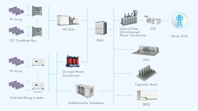
Consider whether the installation will include on-site generation such as photovoltaic panels or small wind turbines. Battery storage systems change the calculation further. These systems require dedicated circuits, appropriate metering, and control logic to manage energy flows between grid, generation, storage, and loads.
Controls should prioritize self-consumption of generated power when economically favorable. During periods of high grid tariffs, stored energy can offset demand. During low-tariff periods, batteries can charge from the grid for later use. The electrical installation must support these switching operations safely and reliably.
Step 3: Design for Reduced Distribution Losses
Apply the barycentre technique to locate distribution boards as close as practical to major loads. Calculate voltage drops for all significant circuits. Specify cable sizes that minimize resistive losses while remaining cost-effective. Consider power factor correction for large inductive loads such as air conditioning compressors.
Harmonic distortion from non-linear loads like LED drivers and switch-mode power supplies requires attention. These harmonics increase neutral conductor currents and generate additional heat in transformers and cables. Filters or oversized neutrals may be necessary depending on the load mix.
Step 4: Establish Control Zones and Meshes
Map the building into control zones based on occupancy patterns and usage schedules. Define which circuits belong to each zone. Establish meshes that connect zones and usages under common control inputs. Occupancy sensors, daylight sensors, time schedules, and temperature setpoints all serve as potential control inputs.
Automatic controls should include manual override provisions. Users need the ability to extend lighting or heating when their needs differ from programmed schedules. Occupancy detection can reset overrides automatically after a timeout period. This prevents forgotten overrides from wasting energy indefinitely.
Step 5: Implement Monitoring and Feedback Systems
Install metering at appropriate points throughout the installation. Fiscal meters at the main intake provide billing data. Sub-meters at distribution boards track consumption by zone or usage category. Circuit-level monitoring offers the finest granularity but adds cost and complexity.
Connect meters to a central monitoring system where practical. Trend data reveals patterns that single readings cannot show. A gradual increase in consumption over months might indicate equipment degradation. Sudden spikes might reveal faults or unauthorized loads. Regular review of this data supports continuous improvement.
Practical Recommendations for Engineers, Installers, and Developers
Energy efficiency gains are lost when good designs meet poor execution. The recommendations below address each project phase separately because different decisions carry weight at different stages.
During the Design Phase
Conduct load segmentation before routing any cables. Identify lighting, socket, HVAC, and dedicated appliance circuits as separate categories. Map these circuits to physical zones within the building. Document expected diversity factors based on realistic usage assumptions rather than worst-case totals.
Calculate voltage drop for all circuits exceeding 80% of total expected consumption. Target voltage drops below 3% for lighting circuits and below 5% for other circuits. These targets exceed minimum code requirements but support measurable efficiency gains.
Position distribution boards using barycentre principles. The ideal location minimizes total cable length weighted by current flow. Practical constraints such as accessibility and building layout will modify this ideal. Document the tradeoffs made and their estimated efficiency impact.
Specify cables with appropriate current ratings for expected loads plus reasonable growth allowance. Oversizing beyond practical needs wastes material and increases embodied carbon. Undersizing creates ongoing energy losses throughout the installation's service life.
During Installation
Route cables by the shortest practical paths. Avoid unnecessary bends that increase pulling tension and may damage conductor insulation. Maintain proper separation between power and data cables to prevent interference.
Terminate all connections to manufacturer specifications. Loose terminations create high-resistance joints that generate heat and waste energy. Verify torque settings match the terminal type and conductor size.
Label all circuits clearly at the distribution board. Include circuit function, protected area, and rated current. This documentation supports future troubleshooting and modification without requiring exploratory disconnection.
During Commissioning
Test all protective devices for correct operation. Verify that circuit breakers trip at their rated thresholds. Confirm that discrimination between upstream and downstream devices functions as designed.
Commission all automatic controls and verify correct operation. Occupancy sensors should activate lights within specified detection zones. Time schedules should match building usage patterns. Override functions should work as intended.
Record baseline energy consumption for comparison against future readings. Document meter readings at commissioning to establish starting points for trend analysis.
During Ongoing Operation
Review energy consumption data at regular intervals. Monthly reviews catch seasonal variations. Annual reviews reveal long-term trends. Compare actual consumption against design predictions and investigate significant deviations.
Reassess efficiency when building usage changes. New occupants, different operating hours, or additional equipment all affect consumption patterns. Adjust control settings and consider infrastructure modifications when changes are substantial.
Maintain all equipment according to manufacturer schedules. Dirty filters in HVAC systems increase energy consumption. Degraded lamp output in older lighting may prompt users to add supplementary fixtures. Proactive maintenance preserves designed efficiency levels.
Conclusion
Energy-efficient homes are built through intentional electrical installation design. Distribution boards, circuit planning, and real-time monitoring shape long-term energy behavior more than individual appliances. The system works as a whole, with each component supporting the others. Manufacturers like CHINT provide compatible components that fit into a cohesive system, helping homeowners and builders achieve measurable efficiency gains from day one.